Compact fiber optic geometry for a counter-chirp FMCW coherent laser radar
a fiber optic geometry and coherent laser technology, applied in the field of noncontact precision optical sensors, can solve the problems of inability to achieve precision measurement of dimensions inside the chassis easily with known open beam systems, and the optical sensor head prevents application in limited access areas and tight places, so as to achieve the effect of substantially reducing the uncertainty of composite absolute distance measuremen
- Summary
- Abstract
- Description
- Claims
- Application Information
AI Technical Summary
Benefits of technology
Problems solved by technology
Method used
Image
Examples
example 1
Compact Counter-Chirp Geometry
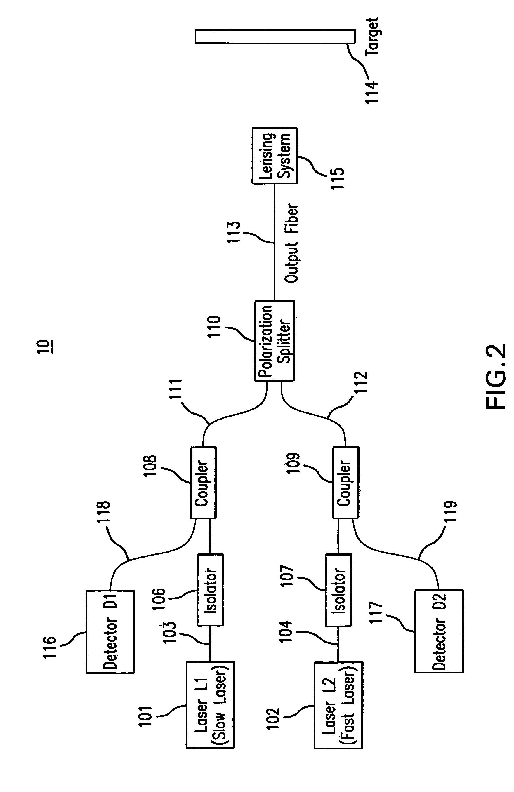
[0058] This disclosure presents a technique for using polarization maintaining (PM) optical fiber components in a polarization diplexing scheme to construct a version of the dual chirp coherent laser radar that is totally immune to environmental effects. FIG. 2 illustrates such a laser radar optical configuration, 10. The laser light is generated by two PM fiber pigtailed laser diodes (101, 102). In a related aspect, laser light may be generated by a fiber laser or solid-state laser source. The light from laser L1, 101, designated the slow laser, is aligned with the corresponding slow axis of the PM fiber, 103, The light from laser L2, 102, designated the fast laser, is aligned with the corresponding fast axis of the PM fiber, 104. The light from each laser passes through a corresponding fiber optic optional isolator (106, 107) to prevent back-reflected light from disrupting the lasers' tuning characteristics. In a related aspect, the isolator may be a...
example 2
Compact Counter-Chirp Geometry, Including Reference Arm Standard
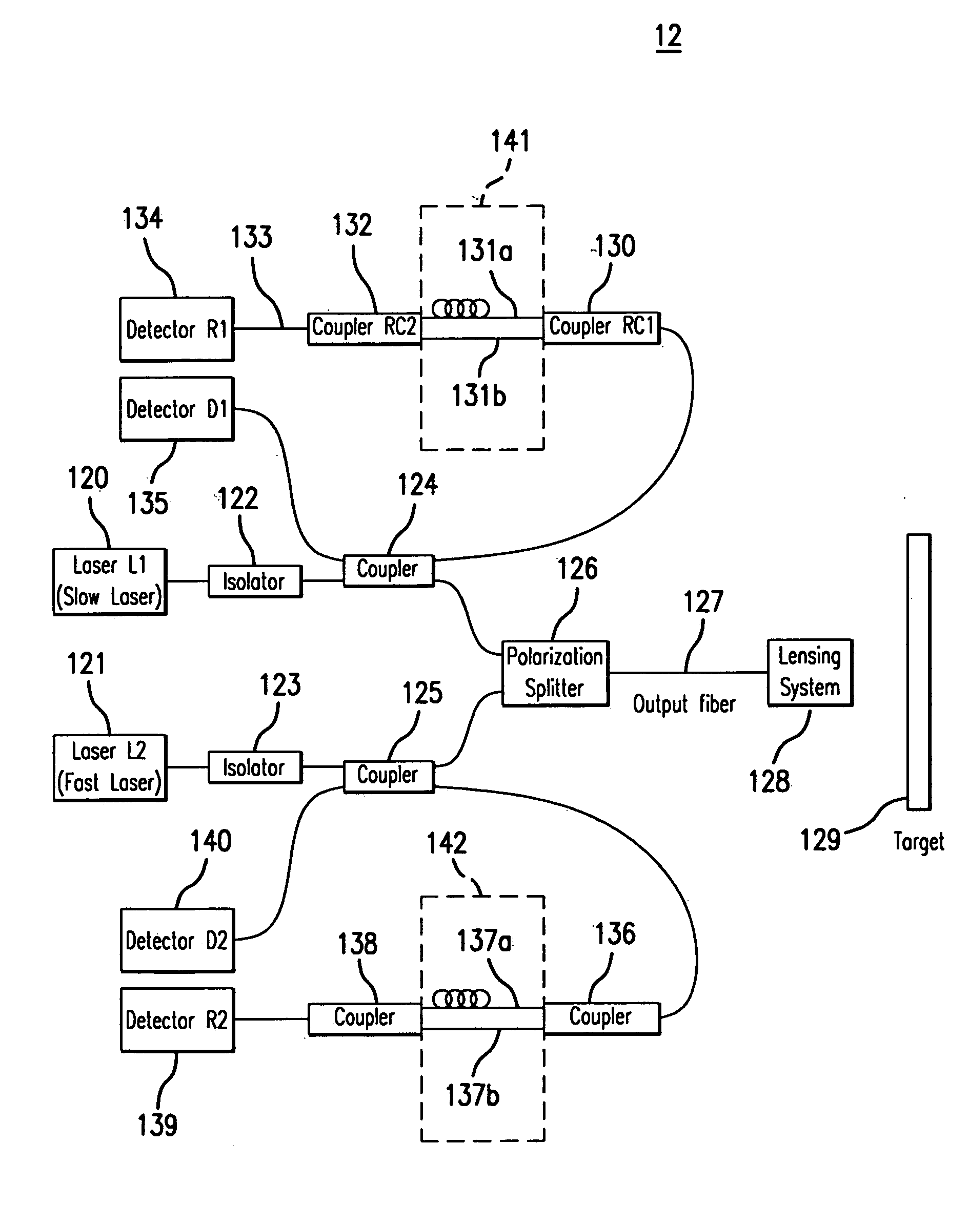
[0064] For precision measurements it is necessary to include a reference arm standard both for absolute ranging accuracy and to help linearize the lasers' chirp waveforms. This reference standard can take the form of a fiber optic interferometer in a Mach Zehnder configuration (e.g., see U.S. Pat. No. 4,552,457). Alternatively, a Michelson interferometer configuration may also be used (e.g., see U.S. Pat. No. 4,278,351). FIG. 5 illustrates the basic geometry, 12, with reference arm standards for each laser (120, 121). In this geometry, 12, the light from laser L1, 120, after passing through the isolator, 122, is received by a fiber coupler, 124. This coupler, 124, has a nominal 50 / 50 splitting ratio. Other splitting ratios are possible but are less desirable in terms of system performance. The light energy that is directed to the target is split into the signal and LO paths and detected as described in Example 1. The r...
example 3
Compact Counter-Chirp Alternative Geometry, Including Reference Arm Standard
[0067] In an alternate fiber geometry, 15, the invention can be configured as illustrated in FIG. 7. In this configuration, 15, the light from lasers L1, 150, and L2, 151, after passing through their corresponding isolators (152, 153), are combined by a polarization splitter, 154. The light from the two lasers (150, 151) are received by a fiber optic coupler, 155, such that their orthogonal polarizations are preserved. The light energy that is directed to the target, 158, is split into the signal and the LO paths as described in Example 1 and is directed to the detectors D1, 165, and D2, 166, by means of the passing through the coupler, 155, again. A second polarization splitter, 159, directs the light in the LO and signal path from laser L1, 150, to detector D1, 165 and the light in the LO and signal path from laser L2, 151, to detector D2, 166. In a similar manner, light from the two lasers (150, 151) is ...
PUM
 Abstract
Description
Claims
Application Information
 - R&D
- Intellectual Property
- Life Sciences
- Materials
- Tech Scout
- Unparalleled Data Quality
- Higher Quality Content
- 60% Fewer Hallucinations
Browse by: Latest US Patents, China's latest patents, Technical Efficacy Thesaurus, Application Domain, Technology Topic, Popular Technical Reports.
© 2025 PatSnap. All rights reserved.Legal|Privacy policy|Modern Slavery Act Transparency Statement|Sitemap|About US| Contact US: help@patsnap.com


