
Optical disc driving apparatus and land pre-pit detection method using the same

a technology of optical discs and pre-pit detection, applied in the direction of digital signal error detection/correction, instruments, recording signal processing, etc., can solve the problems of affecting the detection effect of optical discs, noise components can be misjudged, and error tests can take a significant amount of time to complete the testing, so as to achieve optimal balance level and slice level, and increase the detection performance

Inactive Publication Date: 2006-08-17
SAMSUNG ELECTRONICS CO LTD
View PDF8 Cites 4 Cited by
  • Summary
  • Abstract
  • Description
  • Claims
  • Application Information

AI Technical Summary

Benefits of technology

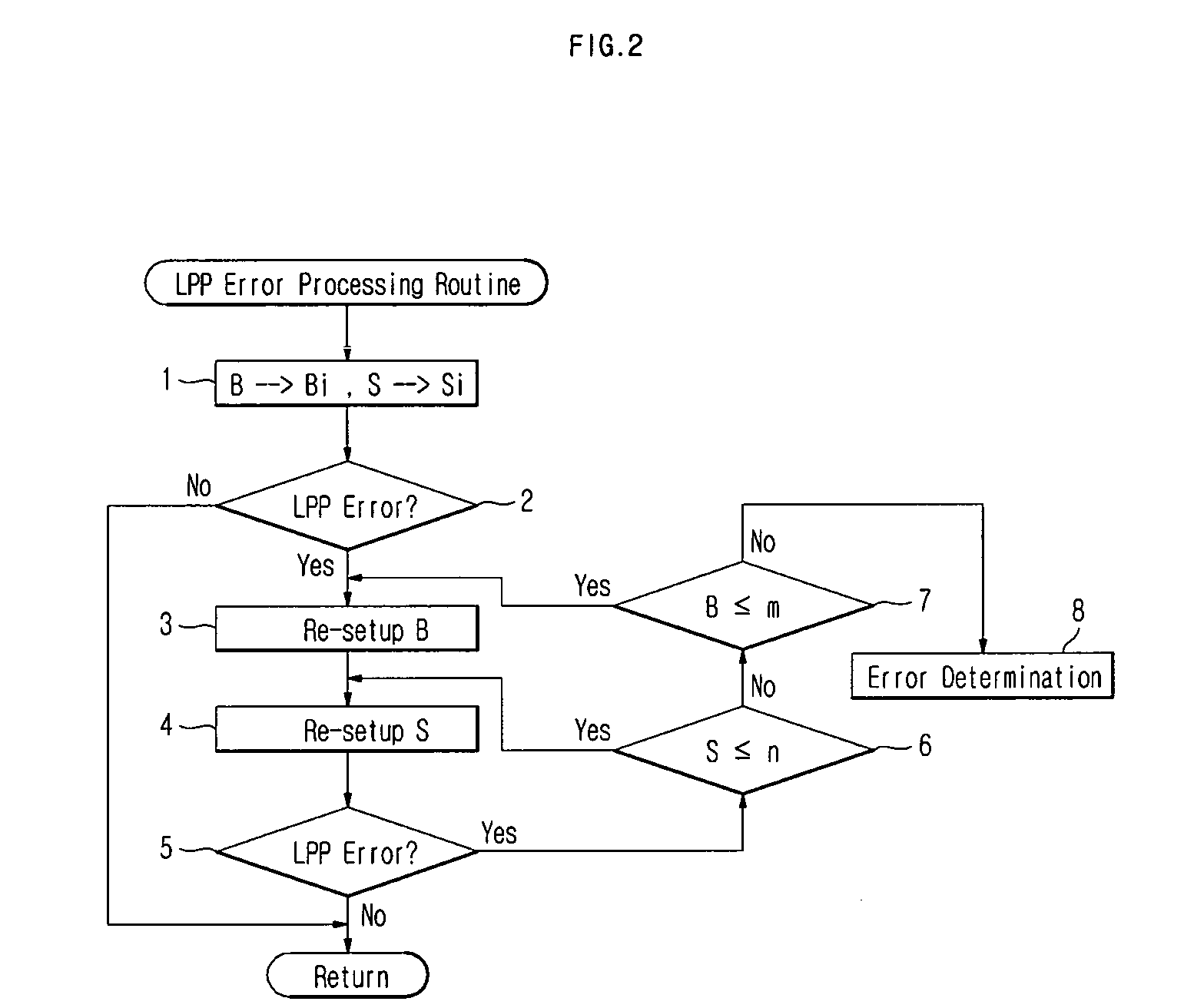
[0014] Various aspects and example embodiments of the present invention provide an optical disc driving apparatus, and a land pre-pit detection method in which an optimal balance level and slice level can be quickly ascertained by defining representative values of each zone according to size of a balance level and a slice level, and the optimal balance level and slice level can be applied to the optical disc driving apparatus in real time. Additionally, representative values of each zone according to a balance level, a slice level and a gain of a wobble signal can also be utilized during real-time testing, in order to increase the performance of detecting a land pre-pit.

Problems solved by technology

However, a land pre-pit error may occur.
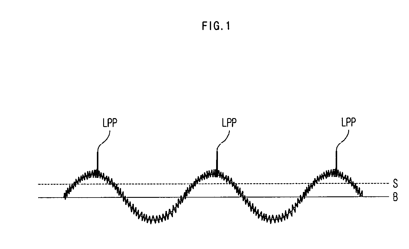
The land pre-pit error is an error in which noise components can be misjudged as the land pre-pit actually pitted on an optical disc, particularly when the noise components occur during the detection of the land pre-pit.
However, the above-mentioned error test method is applied to the optical disc with respect to all applicable balance levels and slice levels.
As a result, the error test can require a significant amount of time to complete the testing as a range of the balance level and slice level increases.
Therefore, it is difficult to apply the conventional error test method to an optical disc driving apparatus which is operated in real-time.

Method used


Image

  • Optical disc driving apparatus and land pre-pit detection method using the same
  • Optical disc driving apparatus and land pre-pit detection method using the same
  • Optical disc driving apparatus and land pre-pit detection method using the same

Examples


Embodiment Construction

[0046] Reference will now be made in detail to the embodiments of the present invention, examples of which are illustrated in the accompanying drawings, wherein like reference numerals refer to the like elements throughout. The embodiments are described below in order to explain the present invention by referring to the figures.

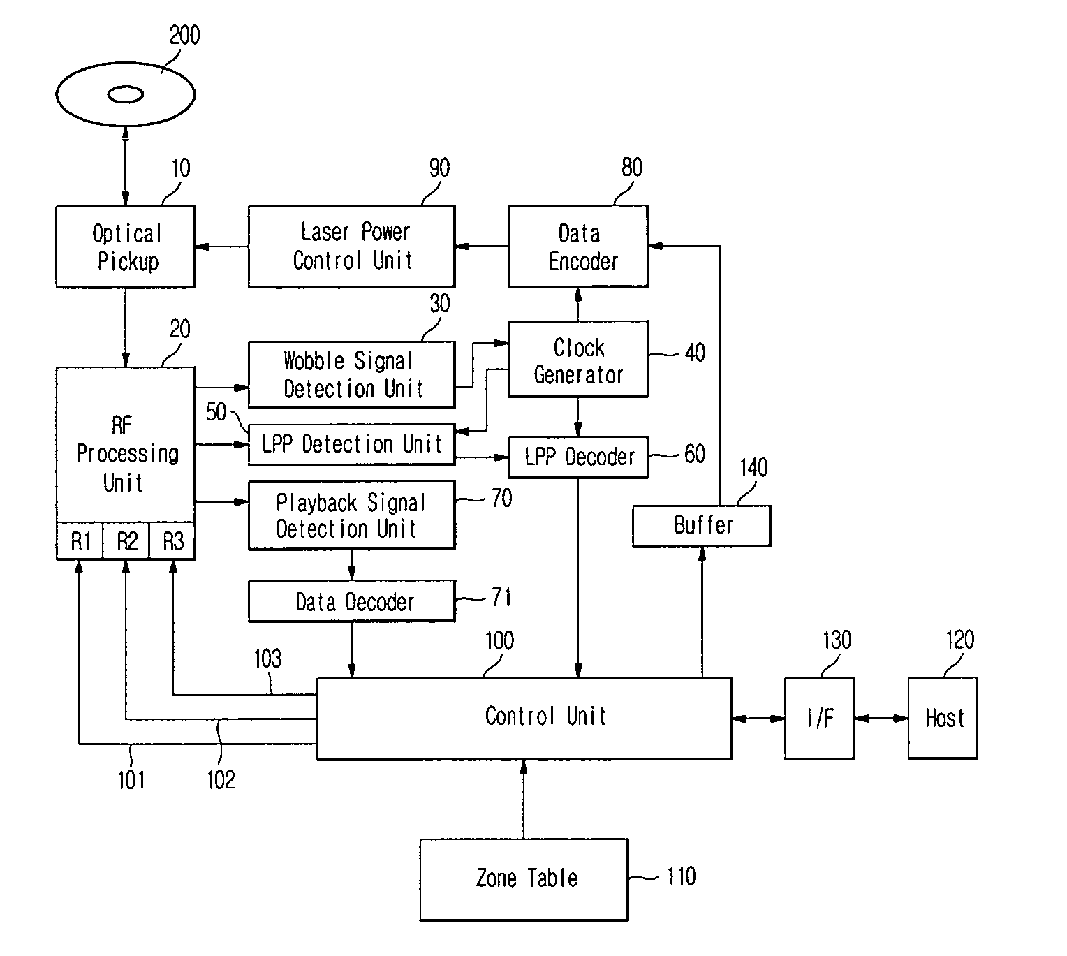
[0047]FIG. 3 is a block diagram showing the configuration of an optical disc driving apparatus according to an embodiment of the present invention. As shown in FIG. 3, the optical disc driving apparatus according to the present invention includes an optical pickup 10, an RF processing unit 20, a wobble signal detection unit 30, a clock generator 40, a land pre-pit (LPP) detection unit 50, an LPP decoder 60, a playback signal detection unit 70, a data decoder 71, a data encoder 80, a laser power control unit 90, a control unit 100, a zone table 110, an interface (I / F) 130 provided to interface with a host 120, and a buffer 140 provided between the data encode...


PUM

PropertyMeasurementUnit
sizeaaaaaaaaaa
sizesaaaaaaaaaa
densityaaaaaaaaaa

Abstract

An optical disc driving apparatus and a land pre-pit detection method are provided for defining determination factors which have an effect on land pre-pit signal detection efficiency. The optical disc driving apparatus comprises an RF processing unit for forming a push-pull signal from an electrical signal acquired through an optical disc; and a control unit for arranging a representative value of determination factors for forming the push-pull signal and testing an error with respect to a land pre-pit (LPP) signal detected from the push-pull signal. As a result, the optical disc driving apparatus is capable of decreasing time for determining the optimal balance level and slice level, and applying the optimal balance level and slice level to the optical disc driving apparatus which operates in real time by defining representative values of each zone according to size of a balance level and a slice level. The optical disc driving apparatus is also capable of increasing performance of land pre-pit detection, by defining representative values of each zone according to a balance level, a slice level and a gain of a wobble signal and by using representative values of each zone when performing real-time test.

Description

CROSS-REFERENCE TO RELATED APPLICATION [0001] This application claims all benefits accruing under 35 U.S.C. §119 from Korean Patent Application No. 2005-76937, filed on Aug. 22, 2005, in the Korean Intellectual Property Office, the disclosure of which is incorporated by reference herein. BACKGROUND OF THE INVENTION [0002] 1. Field of the Invention [0003] The present invention relates to an optical disc driving apparatus, and more particularly, relates to an optical disc driving apparatus for defining determination factors which have an effect on land pre-pit signal detection efficiency, and a land pre-pit detection method using the same. [0004] 2. Related Art [0005] In general, when an optical disc, such as a digital versatile disc (DVD)-R and DVD-RW, is manufactured, a land pre-pit (LPP) is formed on a land to represent location information of the optical disc. The land pre-pit contains address information to identify any location on an unrecorded disc. [0006] A general optical dis...

Claims


Application Information

Patent Timeline
Patent Type & Authority Applications(United States)
IPC IPC(8): G11B5/09G11B7/00
CPCG11B7/0053G11B27/24G11B27/36G11B2220/216G11B2220/218G11B2220/2562G11B19/12G11B20/18
Inventor KIM, BEUNG CHANWOO, JAE HYEON
Owner SAMSUNG ELECTRONICS CO LTD
Learn More