
Sensor system

a sensor and sensor technology, applied in the field of sensor systems, can solve the problems of insufficient displacement, insufficient return force, fragile, etc., and achieve the effect of increasing the mass of the structur

Active Publication Date: 2006-08-17
ANALOG DEVICES INC
View PDF3 Cites 27 Cited by
  • Summary
  • Abstract
  • Description
  • Claims
  • Application Information

AI Technical Summary

Benefits of technology

[0005] In accordance with one aspect of the invention, rather than increasing the mass of the structure, the structure in a sensor system suspends its substrate from some mechanical ground. Motion of the substrate relative to the mechanical ground thus provides the movement information. To those ends, the sensor system includes a base, a substrate, and a flexible member suspended from at least a portion of the substrate. At least a portion of the flexib...

Problems solved by technology

As their name suggests, MEMS devices are very small.
When subjected to an acceleration, the resulting displacement may be insufficient to detect unless the structure is held with very compliant springs.
Very compliant springs, however, are fragile and may not provide enough return force if the structure contacts other internal components (i.e., the structure is more susceptible to stiction problems).
Of course, increasing the size of the structure is inconsistent with the goals of MEMS devices; namely, reducing the overall size of the final device.

Method used


Image

  • Sensor system
  • Sensor system
  • Sensor system

Examples


Embodiment Construction

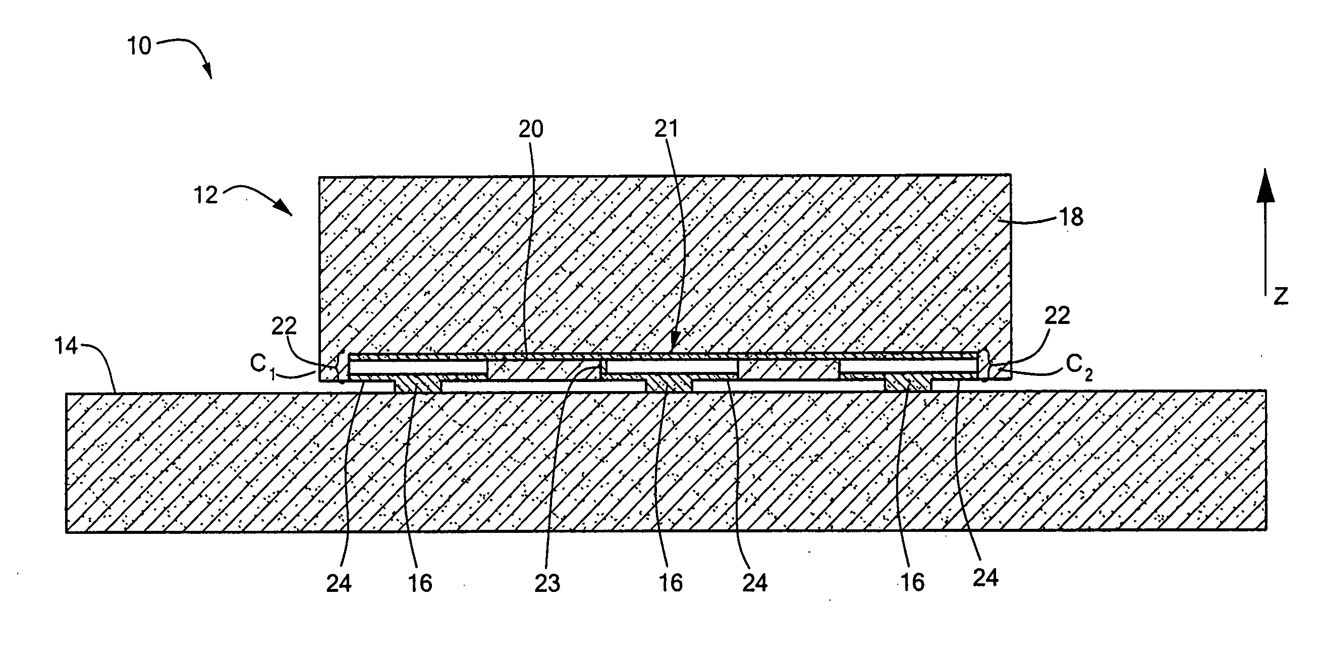
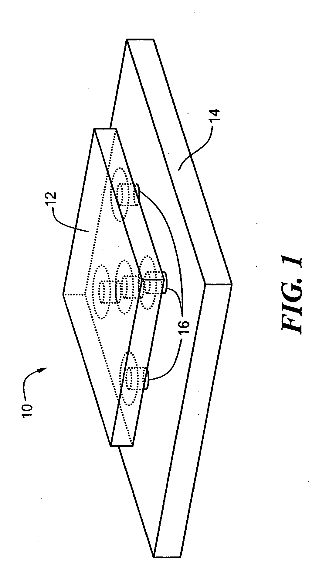
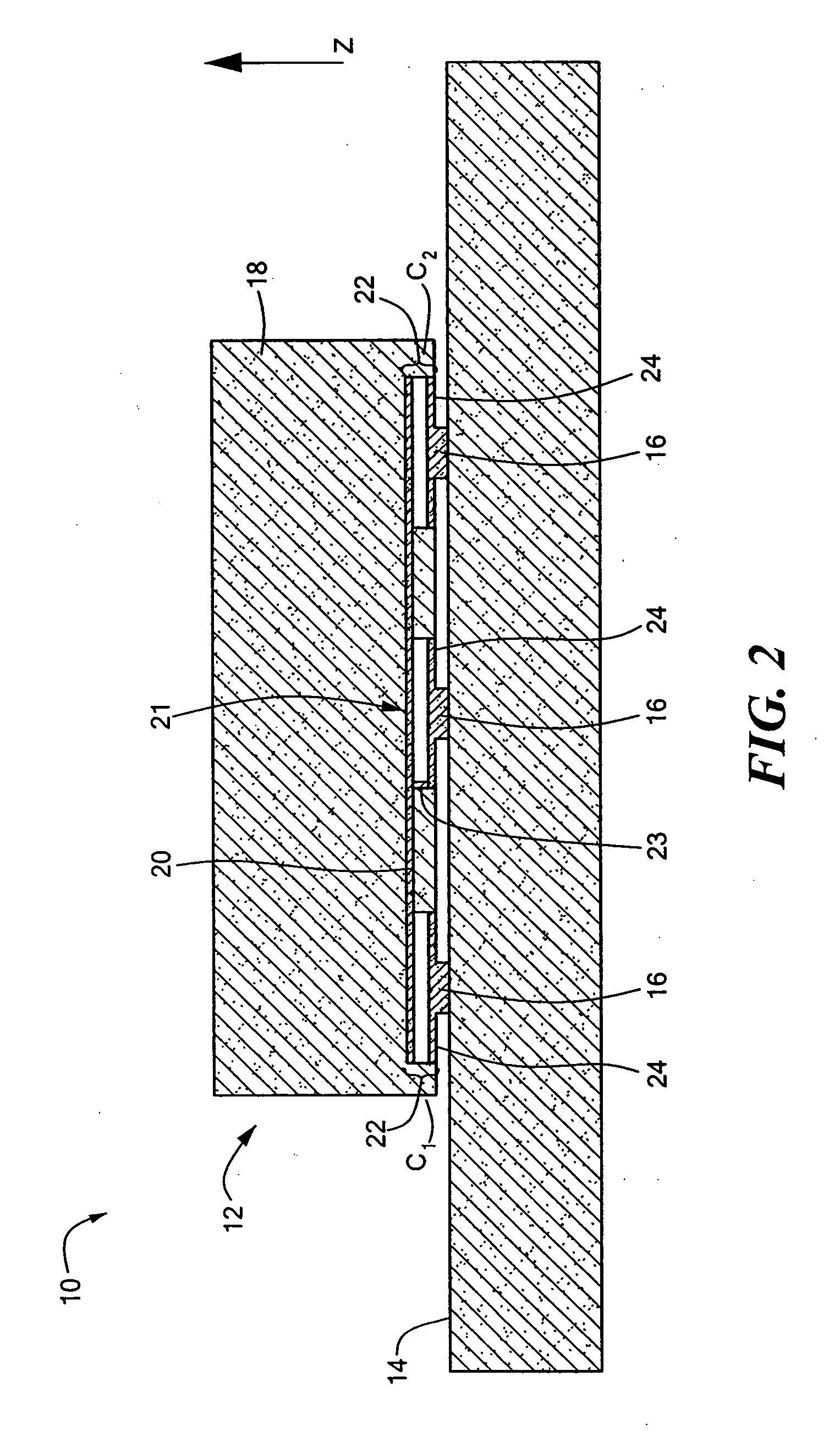
[0025] In illustrative embodiments of the invention, a sensor system movably suspends the substrate of a MEMS chip above a base (e.g., an integrated circuit chip, a package, or a circuit board). Accordingly, rather than monitoring movement of its movable structure (i.e., the portion suspended from the substrate), the sensor system determines acceleration by monitoring movement of the substantial majority of the MEMS chip mass. When compared to prior art MEMS chips of the same size (i.e., those that monitor the suspended portion), this system may have less compliant springs while delivering comparable sensitivity. Less compliant springs, however, typically are more robust. Consequently, the sensor system should be more durable than those of similarly sized MEMS chips and have fewer stiction problems. Alternatively, if desired, the sensor system may have more compliant springs to provide more sensitivity. Even in this latter case, however, the sensor system still should provide the no...


PUM


Abstract

Rather than increasing the mass of the structure, the structure in a sensor system suspends its substrate from some mechanical ground. Motion of the substrate relative to the mechanical ground thus provides the movement information. To those ends, the sensor system includes a base, a substrate, and a flexible member suspended from at least a portion of the substrate. At least a portion of the flexible member is capable of moving relative to at least a portion of the substrate. In addition, the flexible member is secured to the base, thus causing the substrate to be movable relative to the base. Moreover, the mass of the substrate is greater than the mass of the flexible member. The substrate and flexible member are configured to interact to produce a motion signal identifying movement of the base.

Description

FIELD OF THE INVENTION [0001] The invention generally relates to sensor systems and, more particularly, the invention relates to sensor systems having movable structure. BACKGROUND OF THE INVENTION [0002] Microelectromechanical systems (“MEMS,” hereinafter “MEMS devices”) are used in a wide variety of applications. For example, MEMS devices currently are implemented as microphones to convert audible signals to electrical signals, as gyroscopes to detect pitch angles of airplanes, and as accelerometers to selectively deploy air bags in automobiles. In simplified terms, such MEMS devices typically have a movable structure suspended above a substrate, and associated electronics that both senses movement of the suspended structure and delivers the sensed movement data to one or more external devices (e.g., an external computer). The external device processes the sensed data to calculate the property being measured (e.g., pitch angle or acceleration). [0003] As their name suggests, MEMS ...

Claims


Application Information

Patent Timeline
IPC IPC(8): H01L29/84H01L21/00
CPCB60C23/0408B81B3/0018H01G5/18H01G5/40H01L2224/16145H01L2224/73265H01L2224/48091H01L2924/00014
Inventor MARTIN, JOHN R.BROSNIHAN, TIMOTHY J.JUDY, MICHAEL W.ZHANG, XIN
Owner ANALOG DEVICES INC
Learn More