
Random number generator

a random number and generator technology, applied in the field of random number generators, can solve the problem of difficult to predict the output random number compared to a related art device, and achieve the effect of reducing the predictability of random numbers

Inactive Publication Date: 2006-08-10
SANYO ELECTRIC CO LTD +1
View PDF7 Cites 12 Cited by
  • Summary
  • Abstract
  • Description
  • Claims
  • Application Information

AI Technical Summary

Benefits of technology

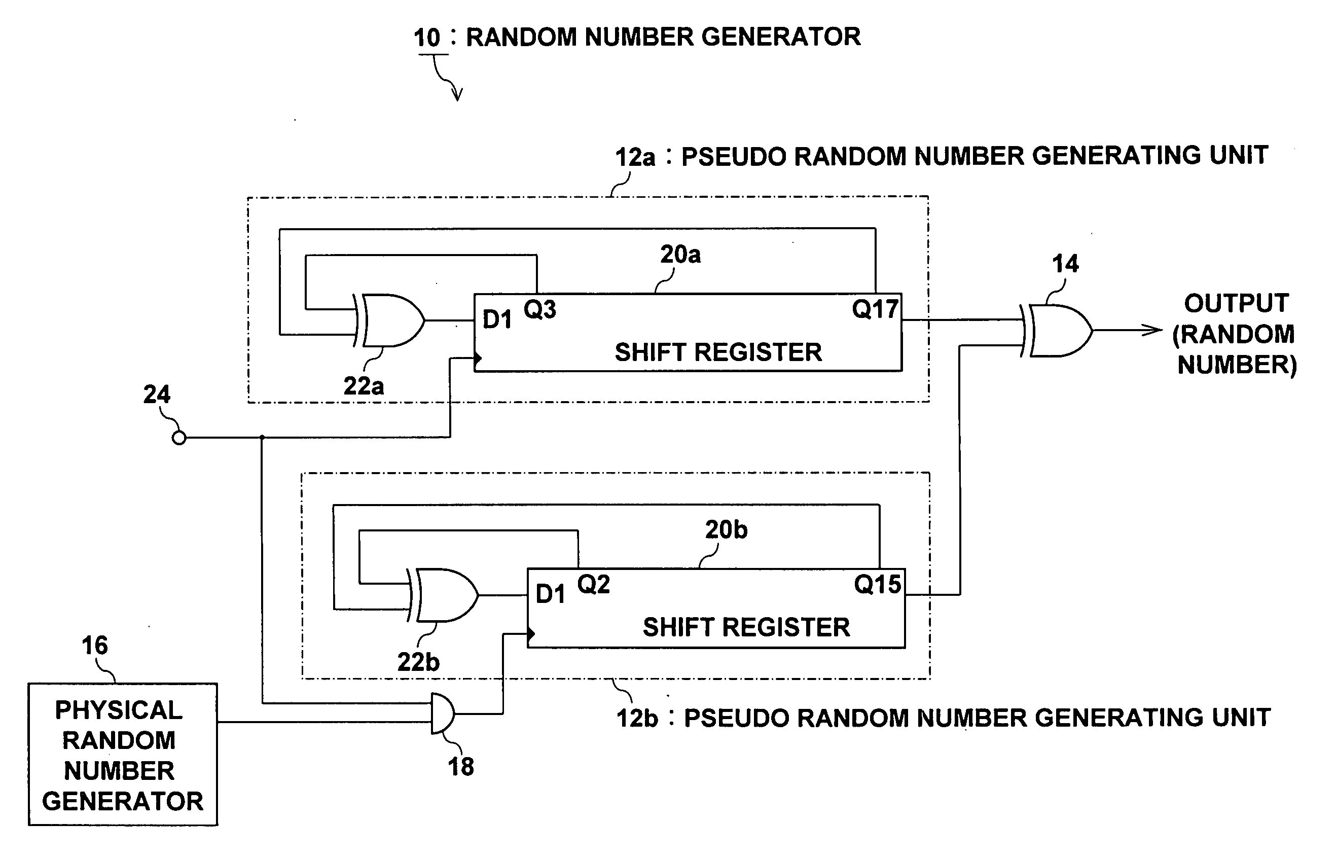
The present invention is a random number generator that reduces predictability of random numbers and makes it difficult to predict the output random number. It includes a plurality of pseudo-random number generating units, an output random number generating unit, a physical random number generating unit, and a switching unit. The switching unit switches whether or not to use a pseudo-random number based on a physical random number. This results in a more secure and unpredictable random number generation. The physical random number is not used as a direct output random number, making it difficult to predict the output random number. The switching unit can also switch whether or not to input a clock signal to the pseudo-random number generating unit. Overall, this random number generator provides a more secure and unpredictable way to generate random numbers.

Problems solved by technology

Also, since a physical random number is not used as a direct output random number, it becomes difficult to predict the output random number compared to a related art device, even if some operation is applied to the physical random number generating unit from outside.

Method used


Image

  • Random number generator
  • Random number generator
  • Random number generator

Examples


first embodiment

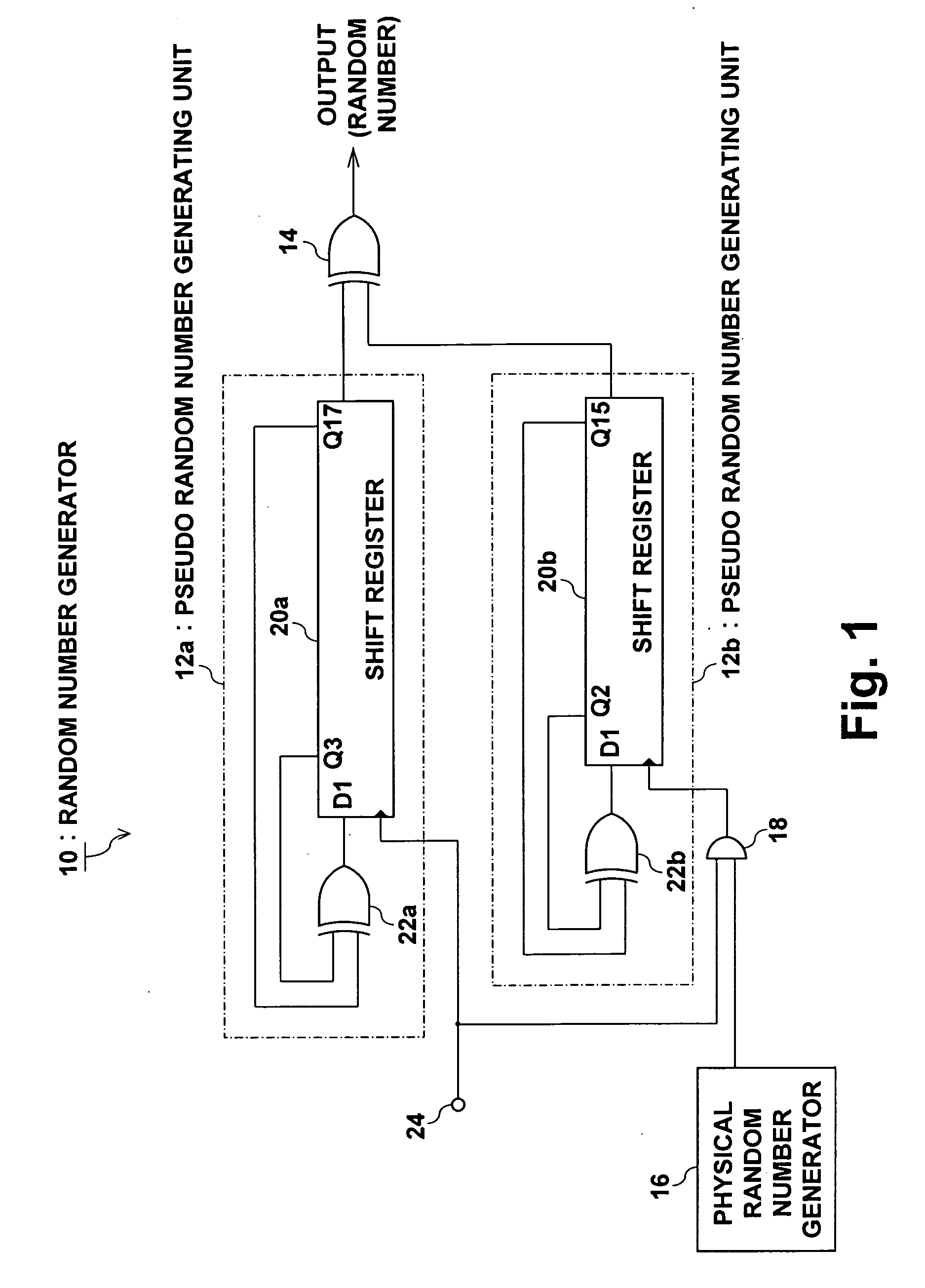
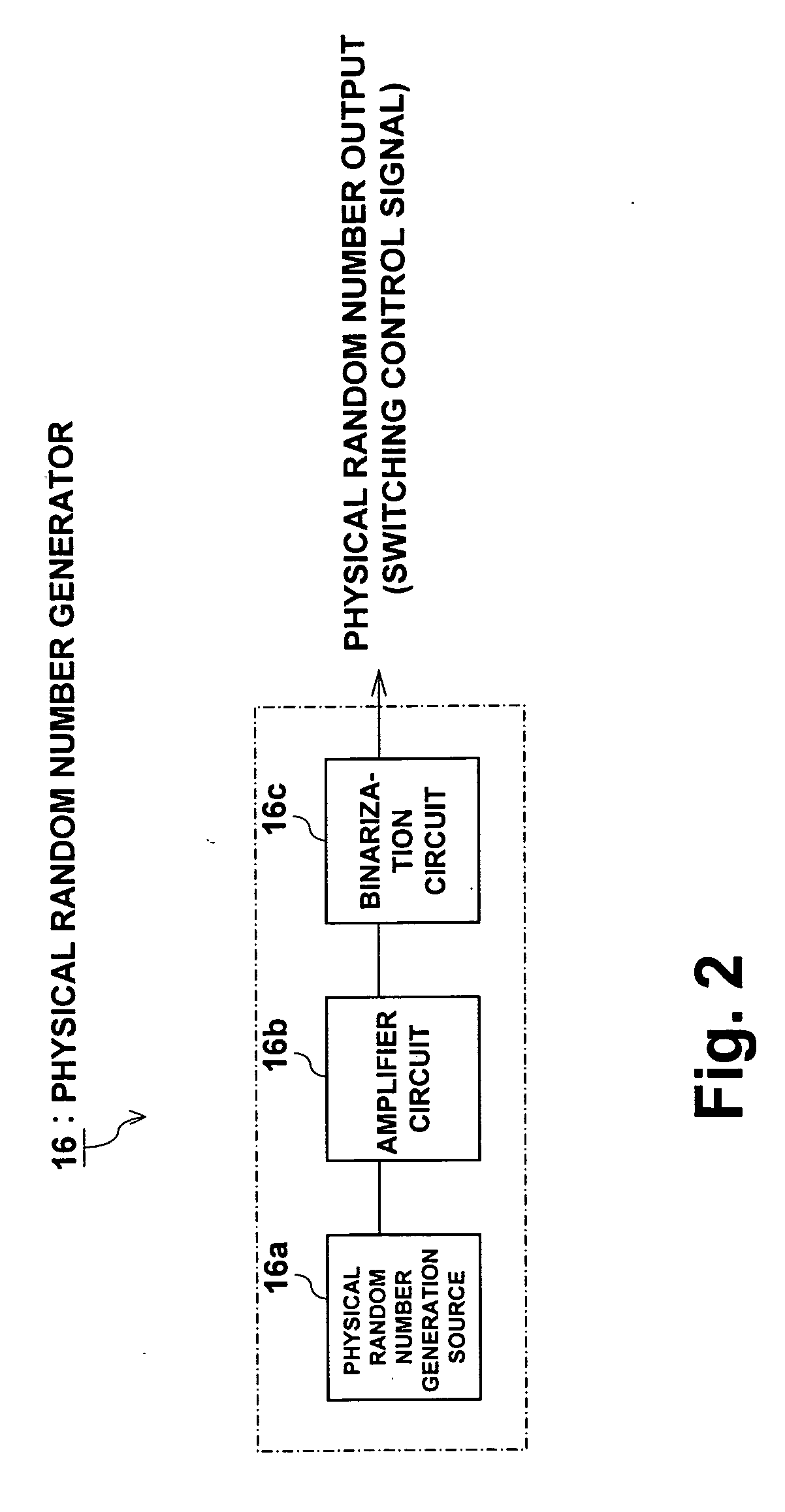
[0013]FIG. 1 is a drawing showing the structure of a random number generator 10 of this embodiment, and FIG. 2 is a structural drawing of a physical random number generator 16. The random number generator 10 is comprised of two pseudo-random number generating units 12a and 12b, an output random number generating unit 14, a physical random number generating unit 16, and a switching unit 18. Of these components, the pseudo-random number generating units 12a and 12b respectively comprise shift registers 20a, 20b including a plurality of flip-flops that are successively connected, and EXOR gates 22a, 22b for outputting an exclusive-OR of output values from a specified plurality of tap positions, and are configured as linear shift register code generators for outputting a random number of a specified M-sequence. With the example of FIG. 1, the shift register 20a has 17 flip-flops, is a 17 stage shift register for performing bit shift in response to a clock signal, and generates a feedbac...

second embodiment

[0017]FIG. 3 is a drawing showing the structure of a random number generator 30 of a this embodiment. Here, structural elements that are the same as in the above-described embodiment have the same reference numerals, and description of duplicate sections is omitted.

[0018] With the above described first embodiment, a logical AND of a physical random number output from the physical random number generator 16 and a shared clock signal from the signal source 24 is input to the pseudo-random number generating unit 12b as a clock signal, but with this embodiment a clock signal to the pseudo-random number generating unit 12b is actually the physical random number output from the physical random number generator 16. With this embodiment, the physical random number generator 16 is equivalent to a switching unit. The clock signal CK of the pseudo-random number generating unit 12a is input independently from the physical random number output. With this structure also, the same effects as with...

third embodiment

[0020]FIG. 4 is a drawing showing the structure of a random number generator 40 of this embodiment. Here, structural elements that are the same as in the above-described embodiment have the same reference numerals, and description of duplicate sections is omitted.

[0021] With this embodiment, whether or not a pseudo-random number generated by the pseudo-random number generating unit 12b is input to the output random number generating unit 14 is controlled using a switching unit 48. With the example of FIG. 4, output of the pseudo-random number generating unit 12b is input to the output random number generating unit 14 via a switching unit 48 configured as an AND gate. In the switching unit 48, a logical AND of the physical random number output from the physical random number generator 16 and the output of the pseudo-random number generating unit 12b is acquired, and this logical AND is input to the output random number generating unit 14. Specifically, when the physical random numbe...


PUM


Abstract

A random number generator comprising a plurality of pseudo random number generating units that can respectively output random numbers in specified pseudo random number systems, an output random number generating unit that generates output random numbers based on outputs from a plurality of pseudo random number generating units, a physical random number generator that generates physical random numbers, and a switching unit for switching between the necessity and the non-necessity of updating output values from pseudo random number generating units based on physical random numbers generated by the physical random number generator. Based on which pseudo random number system an output random number is generated is randomly switched based on a physical random number, making it very difficult to predict a random number compared with a conventional one.

Description

FIELD OF THE INVENTION [0001] The present invention relates to a random number generator, and particularly to a random number generator suitable for an encryption algorithm. DESCRIPTION OF THE RELATED ART [0002] With encryption algorithms, a random number is often used to ensure security. As a random number in this case, generally speaking a pseudo-random number is used that is typified by an M-sequence (Maximum Length Code) or the like. M-sequence code can be generated using a known linear shift register code generator. Also, as a random number other than the above described pseudo-random number, there is known a physical random number generated using natural phenomena such as the fact that nuclear decay is random, or electrical noise. In encryption algorithms also, there are also cases where this physical random number is used instead of the above described pseudo-random number (for example, Japanese Patent Laid-open No. 2000-66592). [0003] However, a pseudo-random number typified...

Claims


Application Information

Patent Timeline
Patent Type & Authority Applications(United States)
IPC IPC(8): G06F7/58G09C1/00H03K3/84
CPCG06F7/588G06F7/584
Inventor ONAYA, MASATOTAMAKI, HARUOIKETANI, AKIRA
Owner SANYO ELECTRIC CO LTD
Learn More