Power transmission apparatus

a technology of transmission apparatus and transmission shaft, which is applied in the direction of gear lubrication/cooling, hoisting equipment, gearing elements, etc., can solve the problems of reducing the durability of bearings, and often not providing electromagnetically controlled clutches to reduce manufacturing costs

Inactive Publication Date: 2006-08-10
DENSO CORP
View PDF4 Cites 9 Cited by
  • Summary
  • Abstract
  • Description
  • Claims
  • Application Information

AI Technical Summary

Benefits of technology

[0009] The present invention has been completed to eliminate the drawbacks, of the prior art, mentioned above. It is an object of the present invention to provide a power transmission apparatus in which, unlike the prior art in which the sleeve ring is bent at the rear end and is calked at the front end to secure the bearing after the latter is inserted in the sleeve ring, the shape of the sleeve ring is modified so that the front end of the ring is bent and an annular retainer is fitted to the ring from the rear end thereof and is calked after the bearing is inserted from the rear side of the ring. With this arrangement, no positional deviation of the bearing occurs if an external load is applied to the pulley.

Problems solved by technology

However, an electromagnetic clutch is often not provided to reduce the manufacturing cost.
However, in this arrangement, if an external load is applied in the forward direction of the pulley, the calked portion 5a receives the load, so that sufficient calking strength cannot be obtained.
However, in the case of a conventional resin pulley, heat generated in the bearing 5 tends not to be radiated through the pulley made of resin, thus resulting in reduction of the durability of the bearing.
However, in the resin pulley as disclosed in JPP '620, the extension of the sleeve ring in the axial direction to provide a large heat radiating surface area of the sleeve ring increases the thickness of the entire pulley, thus leading to an increase in the size of the power transmission apparatus.

Method used


Image

  • Power transmission apparatus
  • Power transmission apparatus
  • Power transmission apparatus

Examples


first embodiment

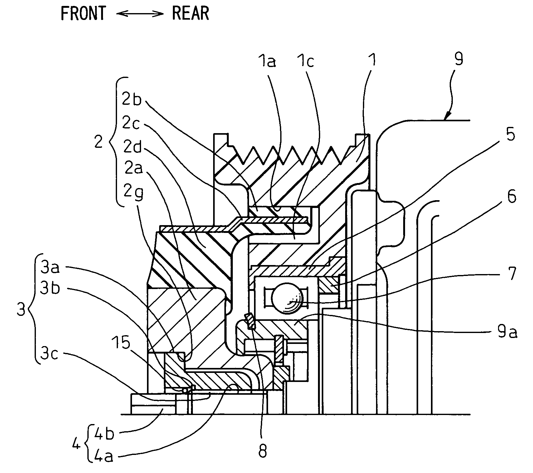
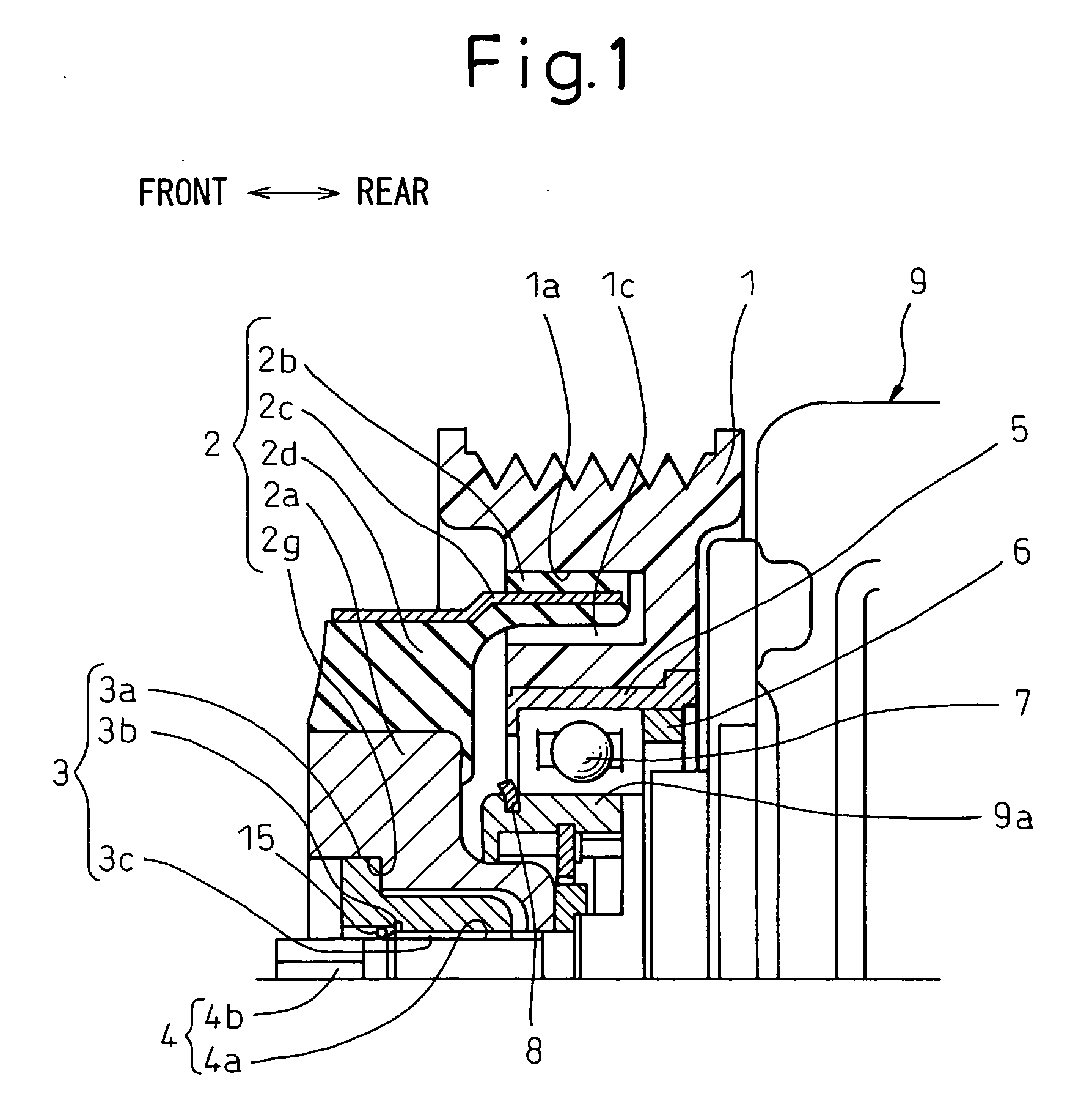
[0040]FIGS. 1 and 2 schematically show a power transmission apparatus according to the present invention. FIG. 1 shows a longitudinal sectional view of an upper half of a power transmission apparatus and FIG. 2 shows an enlarged partial sectional view of a sleeve ring and its surroundings in a power transmission apparatus shown in FIG. 1. In FIGS. 1 and 2, the elements corresponding to those in the prior art shown in FIGS. 11 and 12 are designated with the same reference numerals.

[0041] The structure of the power transmission apparatus shown in FIG. 1 will be discussed below. The power transmission apparatus transmits the external power supplied from an engine, etc., through a belt (not shown) to a compressor (not shown). The power transmission apparatus is comprised of a pulley 1 to which the belt is wound, a hub 2 which connects the pulley 1 to a rotating shaft 4 of the compressor, a torque limiter 3 which connects the pulley 1 to the rotating shaft 4 and breaks the connection whe...

second embodiment

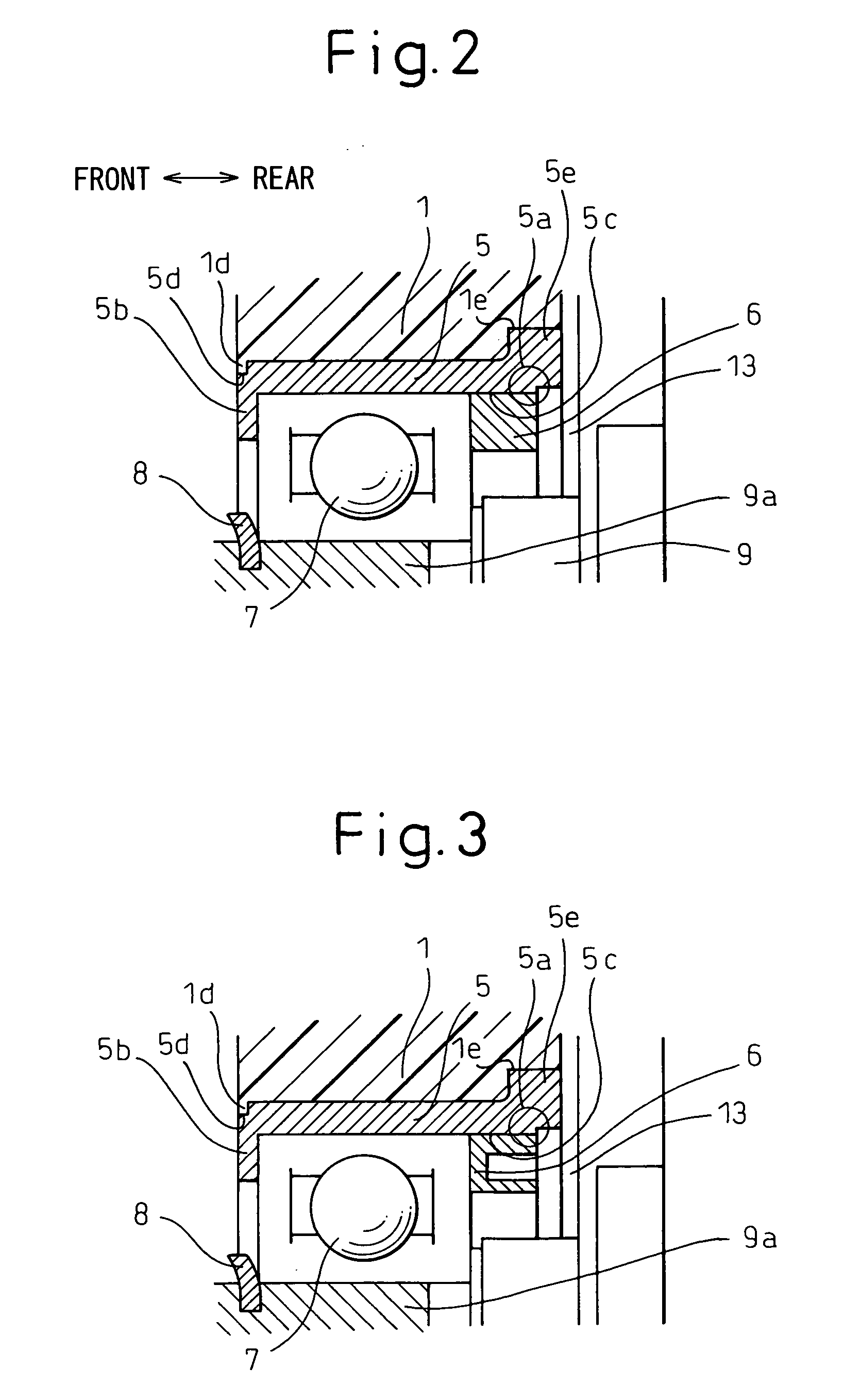
[0060] In a power transmission apparatus according to the present invention, the bearing can be secured to the sleeve ring by means of connecting methods other than calking, such as crimping, adhering or welding, etc.

third embodiment

[0061] In a power transmission apparatus according to the present invention, the following effects can be further expected.

[0062] As the bent portion is made of a separate piece from the sleeve ring body, the sleeve ring and the bent portion can be simplified in shape, and thus the sleeve ring can be more easily machined.


PUM


Abstract

A power transmission apparatus includes a pulley 1 having a belt attached thereto to transmit the rotating drive force, a hub 2 which connects the pulley to a rotating shaft of a driven device, a bearing 7 which rotatably supports the pulley, and a sleeve ring 5 which is fitted and secured to the pulley and attaches the bearing to the pulley to prevent it relatively moving. The sleeve ring is provided, on its first end opposite to the driven device, with a bent portion 5b against which the bearing abuts to restrict further movement of the bearing. An annular retainer 6 is provided on the portion of the bearing adjacent to the drive device. The bearing is secured to the sleeve ring through the annular retainer by calking a second end 5a of the sleeve ring opposite to the first end. The sleeve ring is provided with a projection 5f which projects in the axial direction from the rear surface of the pulley and a casing 9 is provided with an annular groove 9c which at least partly receives therein the projection.

Description

BACKGROUND OF THE INVENTION [0001] 1. Field of the Invention [0002] The present invention relates to a power transmission apparatus, having a torque limiting function, which is particularly useful for a compressor, for an air conditioner in a vehicle, which is always driven by an external power source, such as an engine, through a belt or the like. [0003] 2. Description of the Related Art [0004] A refrigerant compressor for an air conditioner in a vehicle and, in particular, a car air conditioner, is driven by an external drive source, such as an engine, through a belt and a pulley, etc. An electromagnetic clutch may be provided between the compressor and the engine to selectively establish a connection therebetween. However, an electromagnetic clutch is often not provided to reduce the manufacturing cost. In the absence of an electromagnetic clutch, the power transmission mechanism is provided with a torque limiter to prevent the engine from being influenced by trouble on the compr...

Claims


Application Information

Patent Timeline
IPC IPC(8): F16H55/36
CPCF16H55/36F16H55/48F16H57/04
Inventor NOSAKA, MICHIYASUNAGAE, HIROSHIYAMASHITA, MASAHIROTABUCHI, YASUOTADA, YOSHIKITANABE, MITSUHIRO
Owner DENSO CORP
Why Eureka
Try Eureka