
Boiler and low-NOx combustion method

a combustion method and boiler technology, applied in the field of boilers and low-nox combustion methods, can solve the problems of difficult to realize such boilers, and achieve the effects of reducing nox, reducing o2, and reducing co

Active Publication Date: 2006-08-10
MIURA COMPANY LIMITED
View PDF15 Cites 8 Cited by
  • Summary
  • Abstract
  • Description
  • Claims
  • Application Information

AI Technical Summary

Benefits of technology

[0007] The present invention has been made with a view toward solving the above problem in the prior art. An object of the present invention is, therefore, to provide a boiler capable of realizing a reduction in O2, a reduction in NOx, and a reduction in CO. Another object of the present invention is to provide a low-NOx combustion method which helps to achieve a reduction in O2, a reduction in NOx, and a reduction in CO.

Problems solved by technology

However, with the conventional techniques, it is rather difficult to realize such a boiler.

Method used


Image

  • Boiler and low-NOx combustion method
  • Boiler and low-NOx combustion method
  • Boiler and low-NOx combustion method

Examples


Embodiment Construction

[0057] In the following, specific examples of the boiler and the low-NOx combustion method according to the present invention will be described with reference to the drawings.

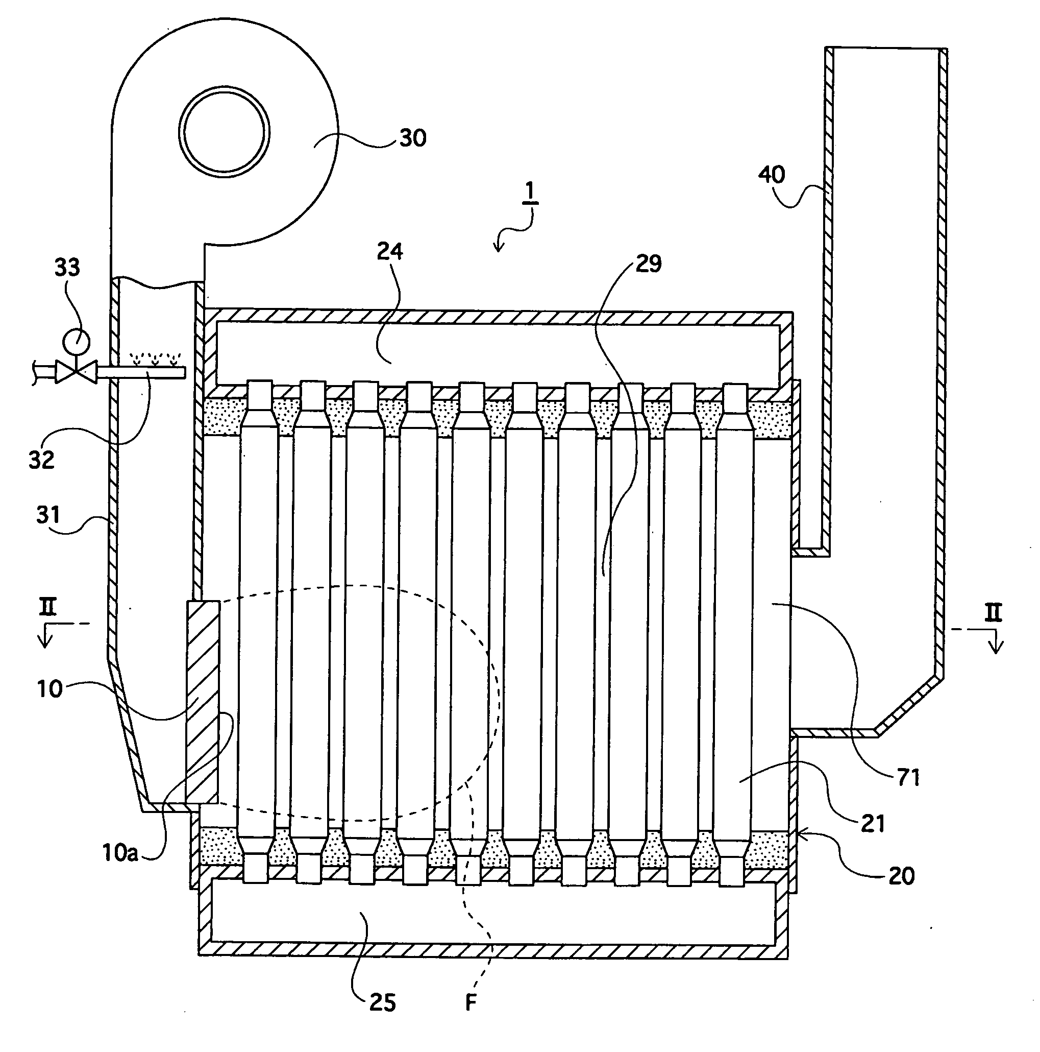
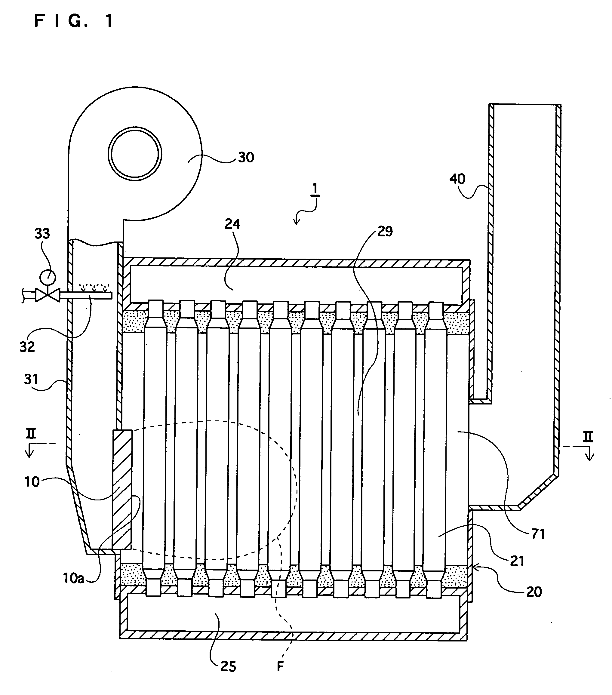
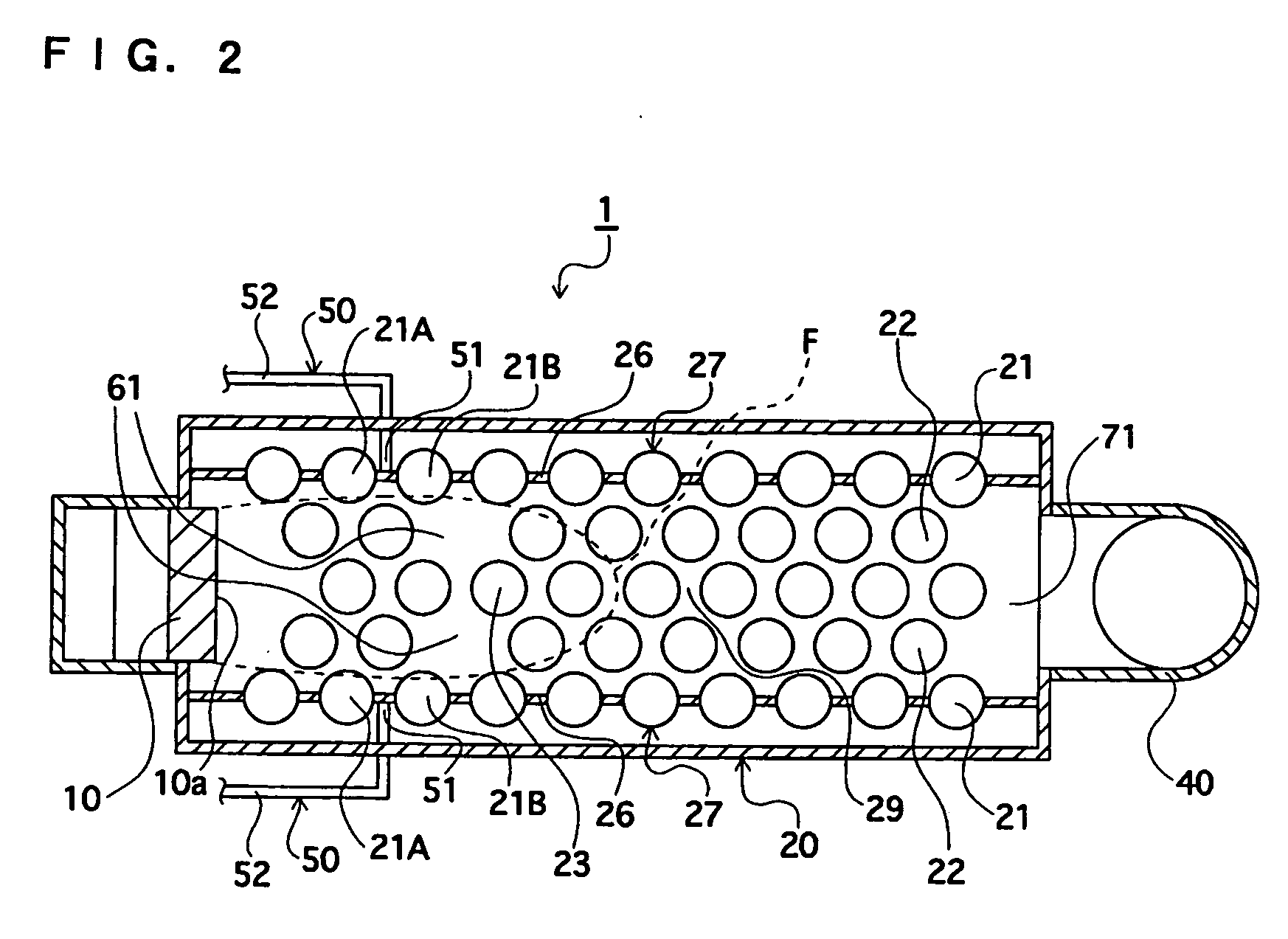
[0058]FIG. 1 is an explanatory longitudinal sectional view of an example of a steam boiler according to the present invention. FIG. 2 is an explanatory cross-sectional view taken along the line II-II of FIG. 1.

[0059] As shown in FIGS. 1 and 2, a boiler 1 of this example is composed of a completely premixed type burner 10 (which corresponds the “premixed gas burner” of the present invention) having a planar premixed gas ejection surface (a flat combustion surface in which premixed gas ejection holes are formed substantially in the same plane), a boiler body 20 formed by using a large number of heat absorbing water tubes (heat transfer tubes) 21, 22, and 23 (which correspond to the “cooling member” of the present invention), a blower 30 provided in order to supply combustion air to the burner 10, a chimney port...


PUM


Abstract

To provide a boiler capable of realizing a reduction in O2, a reduction in NOx, and a reduction in CO. The present invention provides a boiler including: a premixed gas burner, and water tubes in close proximity to the premixed gas burner, characterized in that the premixed gas burner ejects a premixed gas toward the water tubes at a predetermined angle; and the boiler further includes a fuel supply portion capable of supplying at least one of a gas fuel and a premixed gas provided at a position on a downstream side of and spaced apart by a predetermined distance from the premixed gas burner.

Description

BACKGROUND OF THE INVENTION [0001] 1. Field of the Invention [0002] The present invention relates to a boiler and a low-NOx combustion method. [0003] 2. Description of the Related Art [0004] Environmental pollution has long been a serious societal issue, and, also in boilers, there is a demand for a reduction in harmful substances (NOx, CO, soot, etc.). Various harmful substance reducing techniques for boilers have been proposed. For example, a technique is known according to which a cooling member is installed on the downstream side and in the immediate vicinity of the burner (See JP 06-159612 A). [0005] Further, nowadays, in addition to the request to solve environmental pollution, there is a demand for energy saving, etc., and a further reduction in harmful substances is required. That is, to achieve a solution to the problem of environmental pollution and energy saving, there is a demand for a technique to achieve a reduction in harmful substances at a higher level. [0006] More ...

Claims


Application Information

Patent Timeline
Patent Type & Authority Applications(United States)
IPC IPC(8): F23C5/00F24H1/40
CPCF23C6/047F23C2201/401F23D14/02F24H1/40F24H1/403
Inventor YOSHINARI, YUJITANAKA, OSAMUTOKUNAGA, YUKIHIRO
Owner MIURA COMPANY LIMITED
Learn More