
Substrate processing apparatus, control method adopted in substrate processing apparatus and program

a substrate processing and control method technology, applied in the direction of electric heating, electric discharge heating, electric apparatus, etc., can solve the problems of reducing the service life of the scrubbing device, reducing reducing the quantity of discharge gas discharged from the processing chamber, so as to reduce the onus on the scrubbing device, reduce the onus on the scrubbing means, and reduce the effect of the scrubbing discharge gas

Inactive Publication Date: 2006-08-10
TOKYO ELECTRON LTD
View PDF7 Cites 141 Cited by
  • Summary
  • Abstract
  • Description
  • Claims
  • Application Information

AI Technical Summary

Benefits of technology

[0008] However, the discharge gas from each processing chamber in the structure shown in FIG. 24 or 25 is invariably scrubbed via the scrubbing device and is then discharged, regardless of the type of processing executed in the processing chamber. This means that the gas discharged through the roughing vacuum processing or the like, which is discharged under high pressure conditions and does not require scrubbing, too, has to first undergo scrubbing via the scrubbing device before it is released. As a result, the onus placed on the scrubbing device increases, which leads to a reduced service life of the scrubbing device.
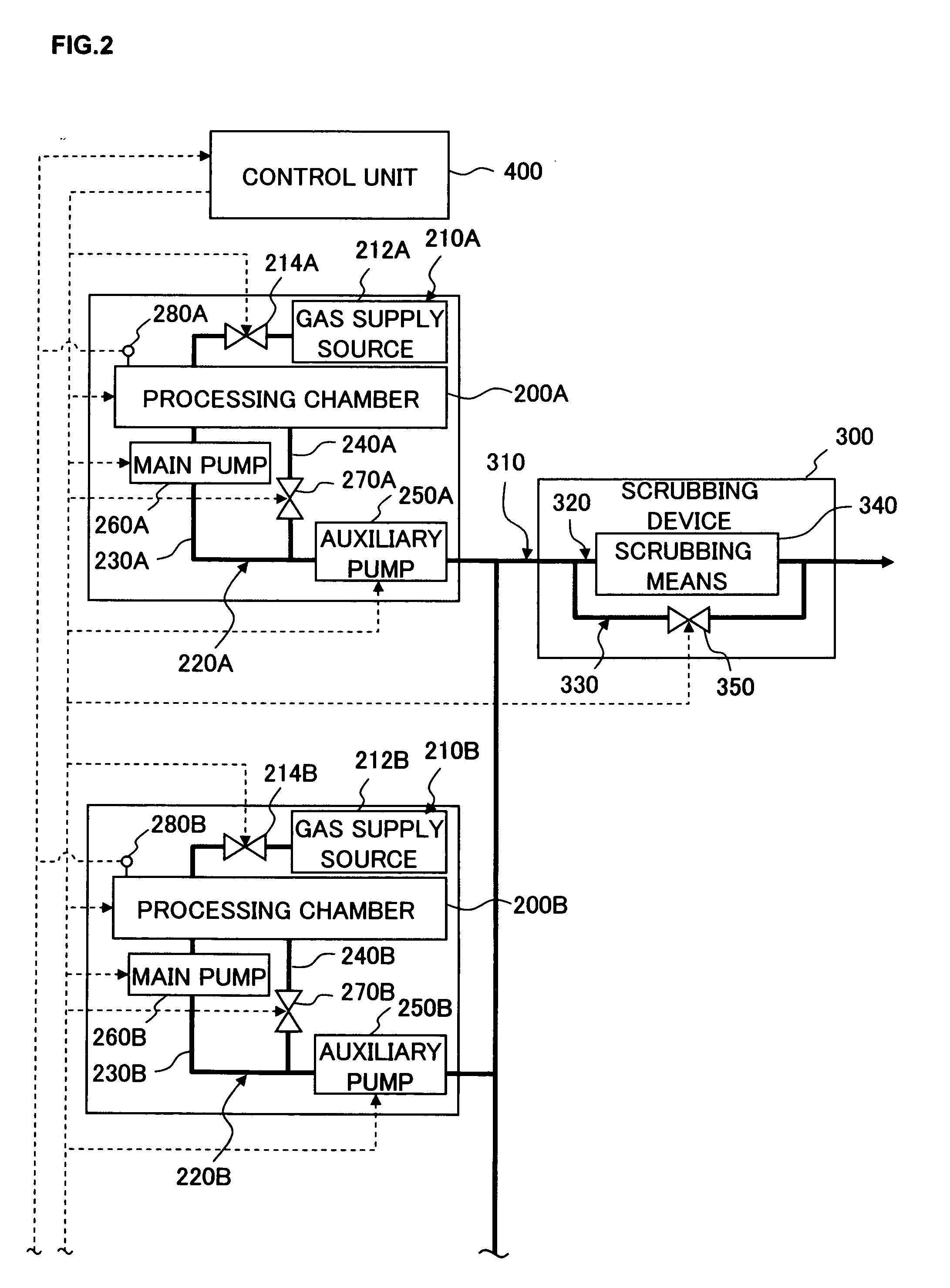
[0027] According to the present invention, the onus on the scrubbing means for scrubbing discharge gas can be reduced, and the energy and the cost required for the discharge gas scrubbing can both be reduced. In addition, when processing is to be executed concurrently at a plurality of processing chambers, the switch-over between the non-scrubbing common discharge system and the scrubbing common discharge system is not allowed to occur while the one type of processing is in progress. As a result, any discharge gas requiring scrubbing is always discharged as scrubbed gas without fail, while reducing the onus placed on the scrubbing means.

Problems solved by technology

As a result, the onus placed on the scrubbing device increases, which leads to a reduced service life of the scrubbing device.
This, in turn, has resulted in a great increase in the quantities of discharge gas discharged from the processing chambers, and ultimately a greater onus on scrubbing devices.
Furthermore, since the discharge gas is scrubbed through, for instance, a heat treatment at a scrubbing device, the level of energy required for the discharge processing rises as the number of scrubbing devices included in the processing system increases.
As a result, the energy efficiency at the plant where such substrate processing apparatuses are installed is lowered and the level of energy consumption at the entire plant rises.

Method used


Image

  • Substrate processing apparatus, control method adopted in substrate processing apparatus and program
  • Substrate processing apparatus, control method adopted in substrate processing apparatus and program
  • Substrate processing apparatus, control method adopted in substrate processing apparatus and program

Examples


Embodiment Construction

[0053] The following is a detailed explanation of preferred embodiments of the present invention, given in reference to the attached drawings. It is to be noted that in the specification and the drawings, the same reference numerals are assigned to components having substantially identical functions and structural features to preclude the necessity for a repeated explanation thereof.

[0054] (Structural Example Adopted in Substrate Processing Apparatus)

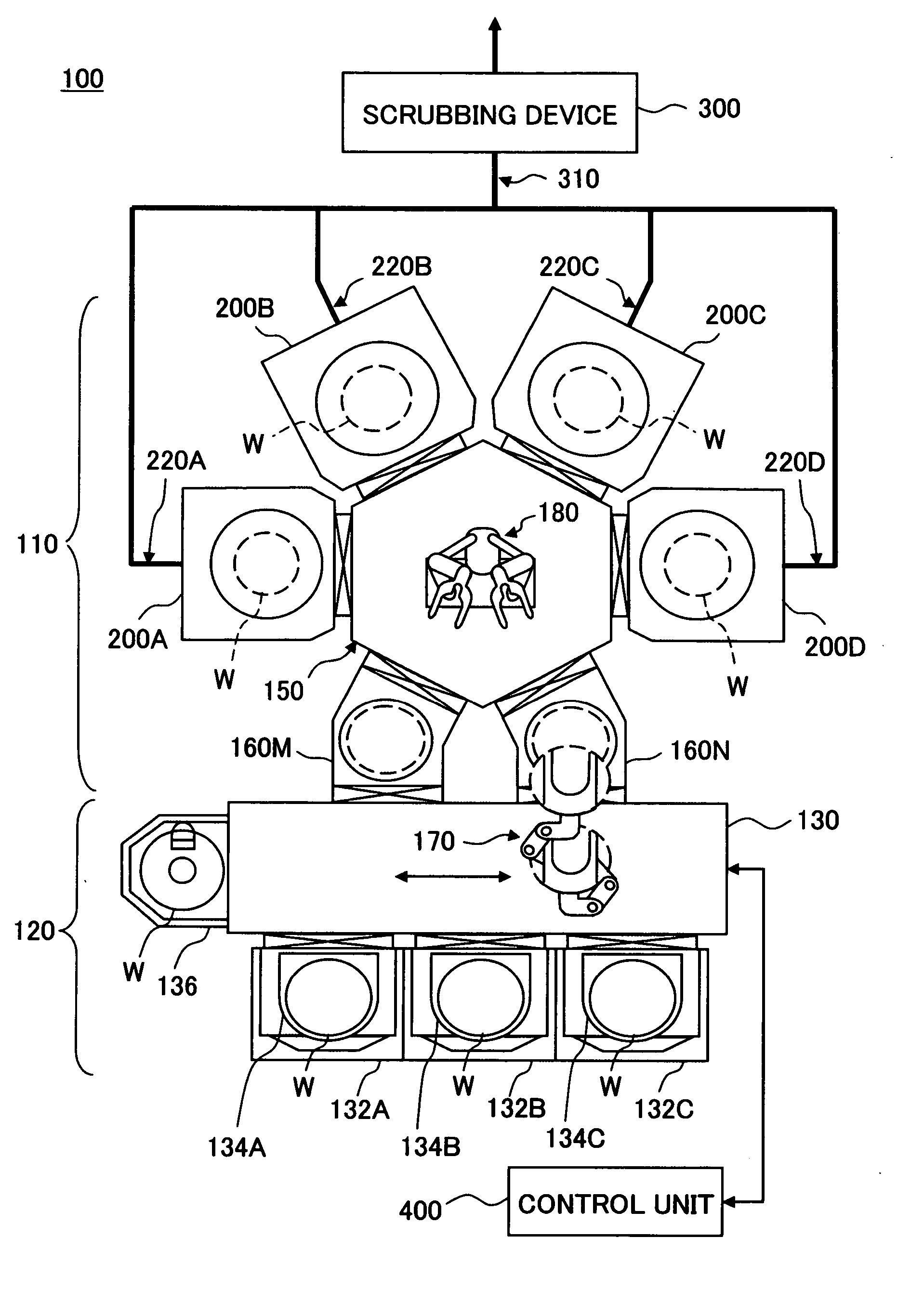
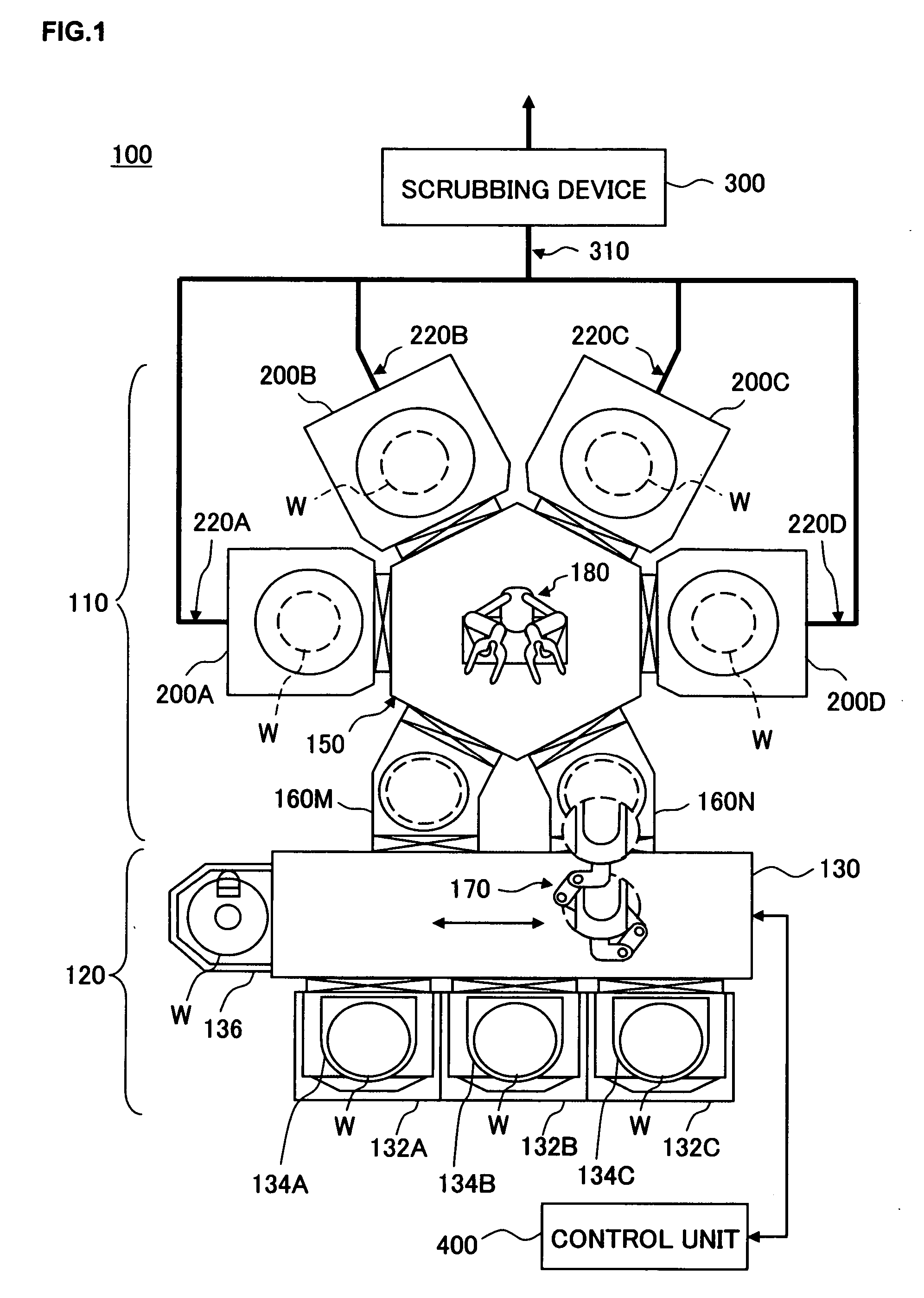
[0055] First, the substrate processing apparatus achieved in an embodiment of the present invention is explained in reference to drawings. FIG. 1 schematically shows the structure adopted in the substrate processing apparatus in an embodiment of the present invention. The substrate processing apparatus 100 comprises a processing unit 110 where various types of processing such as film formation and etching are executed on substrates which may be, for instance, semiconductor wafers (hereafter may be simply referred to as “wafers”) W and...


PUM


Abstract

A substrate processing apparatus according to the present invention comprises a plurality of processing chambers, discharge systems each provided in conjunction with one of the processing chambers and a common discharge system connected with the discharge systems of at least two processing chambers among the discharge systems provided in conjunction with the individual processing chambers. The common discharge allows a switch-over between a scrubbing common discharge system that discharges discharge gas from each processing chamber after scrubbing the discharge gas at a scrubbing means and a non-scrubbing common discharge system that directly discharges the discharge gas from the discharge system of the processing chamber without scrubbing at the scrubbing means. In this substrate processing apparatus, switch-over control is executed to select either the scrubbing common discharge system of the non-scrubbing common discharge system in correspondence to the type of processing executed in the processing chamber.

Description

CROSS REFERENCE TO RELATED APPLICATIONS [0001] This document claims priority to Japanese Patent Application No. 2005-032340 filed Feb. 8, 2005, Japanese Patent Application No. 2005-206376 filed Jul. 15, 2005, U.S. Provisional Application No. 60 / 655,425 filed Feb. 24, 2005, and U.S. Provisional Application No. 60 / 702,990 filed Jul. 28, 2005, the entire contents of which are hereby incorporated by reference.FIELD OF THE INVENTION [0002] The present invention relates to a substrate processing apparatus that includes a scrubbing device for scrubbing discharge gas that is discharged while a substrate such as a semiconductor wafer or a liquid crystal substrate is processed, a control method to be adopted in a substrate processing apparatus and a program. BACKGROUND OF THE INVENTION [0003] Substrate processing apparatuses include plasma processing apparatuses that execute processing such as film formation and etching by using specific types of gases on substrates such as semiconductor wafe...

Claims


Application Information

Patent Timeline
Patent Type & Authority Applications(United States)
IPC IPC(8): H05B7/18
CPCH01L21/6719H01L21/67017
Inventor NAKAMURA, HIROSHIKOBAYASHI, TOSHIYUKIHAYASAKA, SHINICHIROKAISE, SEIICHI
Owner TOKYO ELECTRON LTD
Learn More