
Geographical localisation service

Inactive Publication Date: 2006-08-10
ALCATEL LUCENT SAS
View PDF4 Cites 27 Cited by
  • Summary
  • Abstract
  • Description
  • Claims
  • Application Information

AI Technical Summary

Benefits of technology

[0010] The current invention provides the advantage that it is possible to achieve satisfactory results with few measurements which significantly shortens the time needed for localisation. From the set of measurements, the greatest value is kept simply because the terminal will receive lower values when bad measurement conditions are met, but higher values are rather rare. Thus, the highest value is a very good guess which comes very close to the “true” value.
[0012] According to a preferred embodiment of the invention, the terminal includes all access points signalling an SSID. The SSID serves to identify each available WLAN access point. The fact that all available WLAN access points are considered for the measurements, even those that are not part of the currently used WLAN, advances the fast convergence of the localisation process. The measurement operation is adjusted to accept even signals from WLAN access points which are not suited to process any voice or data communications.
[0015] According to a preferred embodiment of the invention, ten or more signal measurements are taken. Furthermore, in a preferred embodiment of the invention it is possible that only ten to fifteen signal measurements or ten to fifty signal measurements are sufficient to provide accurate and reliable results for localisation. This may be a good compromise in that it both provides reliable results and reduces the time needed for localisation.
[0017] It is also possible that even further information associated with the measurement is recorded in the data base, e.g., weather information, information on the present personnel, information on projects, events, happenings, etc. The processing unit of the localisation server may be adapted with the aid of appropriate software applications to recognise behaviour patterns of a user carrying a terminal, dependant on the additional information. For example, a user may attend other rooms at the beginning of the week than during the week. This may assist a preferable guess in cases where a decision has to be made among two locations with similar signal values from the intensity map, or it may shorten the time needed for the finding of the best matching location since more probable locations are searched first.
[0018] It may be useful for a localisation task to know where a user carrying the terminal has been before the current location. One or more probable paths between a known location where a precedent measurement was made and an unknown location where the current measurement is made may be assumed. It is also known that the orientation of the terminal can affect the strength of a received signal. A user carrying the terminal may block, e.g., with his head or his body, the line-of-sight to an access point, or a different position of the antenna of the terminal may change the signal strength. The input of the orientation of the terminal during the measurement only makes sense if the intensity map stored in a data base also contains information about the influence of the orientation. The knowledge of the path to reach a current location and / or the current terminal orientation may assist in finding the best matching location. The determination of the current location may be forwarded as the number of possible locations from the intensity map is limited. Thus, not the entire data base has to looked through, and in ambiguous cases the decision is facilitated.

Problems solved by technology

While the former technology is practically useless in indoor applications, the poor spatial resolution of the latter prohibits a use in applications that demand high granularity.
The signal strength of data exchanged between a WLAN access point and a mobile terminal decreases with the distance between transmitter and receiver and is even more attenuated by obstacles like walls or doors.
In addition, the signal is affected by multipath effects and interference with persons or furniture.
The great amount of data that has to be processed affords rather complex algorithms and ample storage capacity.
Thus, the implementation of the measurement inside a low cost terminal or low cost CPU is difficult.
As this may be of particular interest for open space areas, it is rather quickly limited with walls and furniture.

Method used


Image

  • Geographical localisation service
  • Geographical localisation service
  • Geographical localisation service

Examples


Embodiment Construction

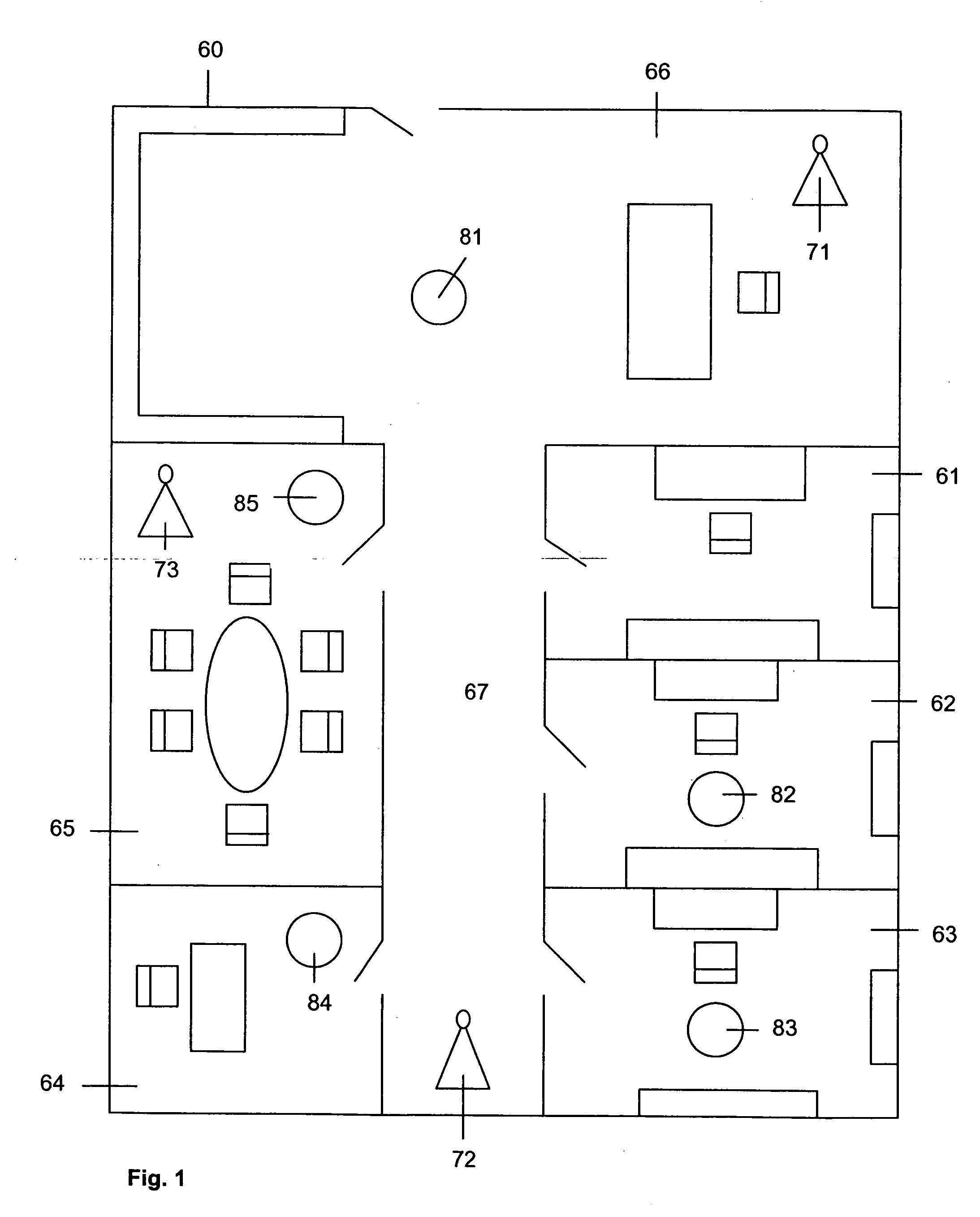
[0023]FIG. 1 is a schematic floor plan diagram where a geographical localisation service is provided. The floor 60 consists of four office rooms 61, 62, 63, 64, a meeting room 65, a reception area 66 and a corridor 67 leading from the reception area 66 to the office rooms 61, 62, 63, 64 and the meeting room 65. The offices 61, 62, 63, 64, the meeting room 65 and the reception area 66 comprise usual office furniture like chairs, desks and racks. A WLAN is installed on the floor 60, comprising three WLAN access points 71, 72, 73 which can be accessed from mobile terminals.

[0024] When a user of a WLAN-enabled mobile terminal is located in proximity to the WLAN access points 71, 72, 73, the terminal receives presence signals from the WLAN access point 71, 72, 73, the signals comprising an SSID which identifies the network the WLAN is associated to. The WLAN access points 71, 72, 73 can be identified based on the use of the SSID. Then the user can choose which WLAN access point he wants...


PUM


Abstract

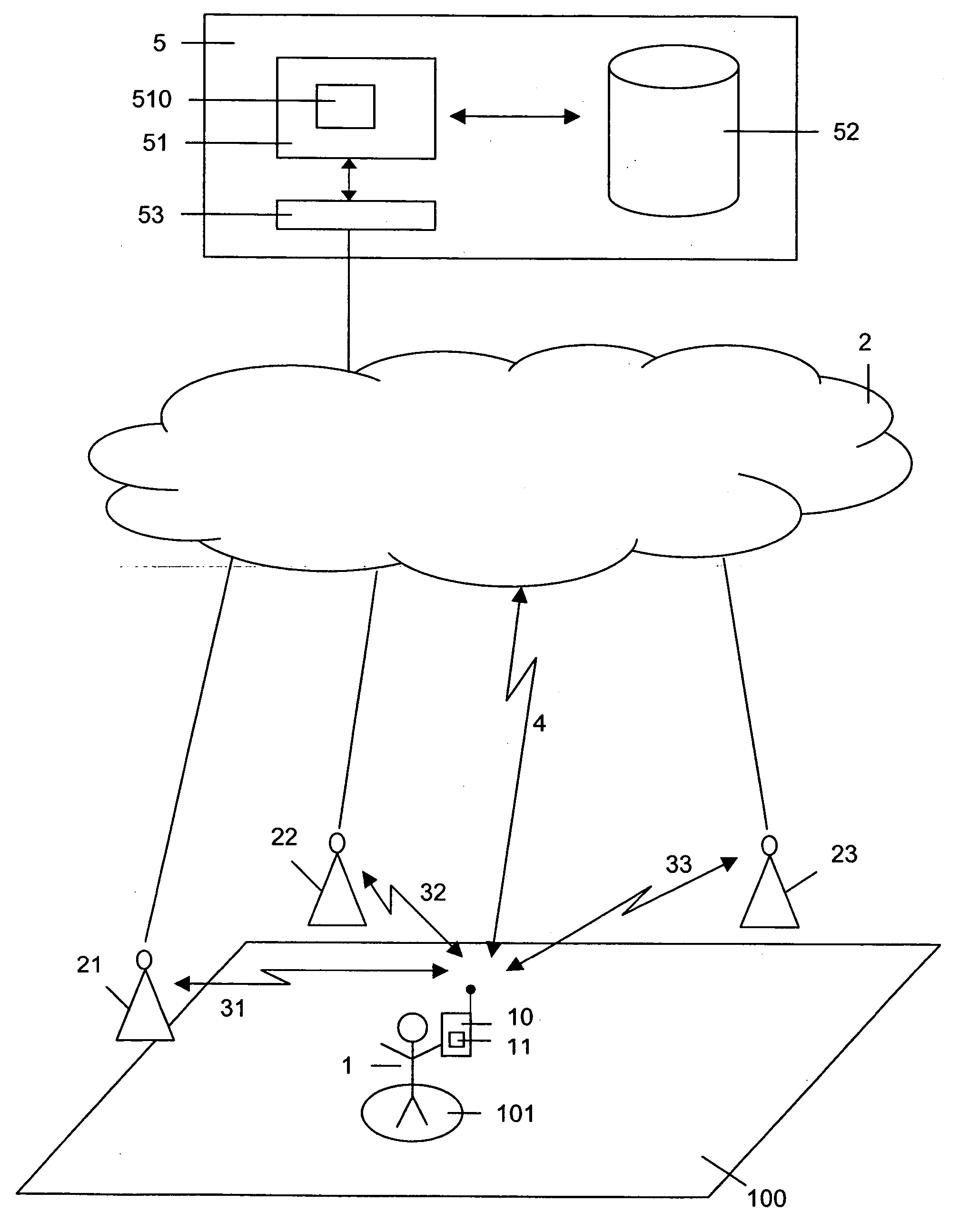
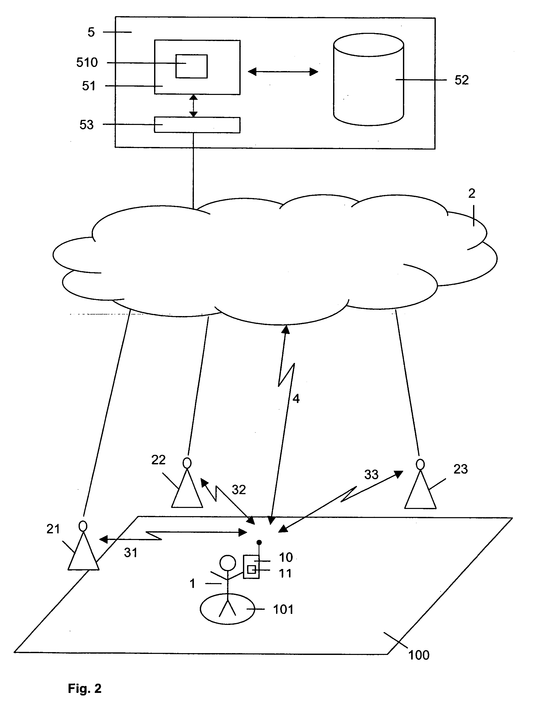
The invention concerns a method of providing a geographical localisation service within a wireless local area network having two or more wireless network access points. The terminal of a user is located at a location of a plurality of locations. The terminal measures at least two times the strength of signals received from two or more wireless network access points. It chooses the strongest signals of the several measurements as valid signal strengths and triggers a localisation server to compare the valid signal strengths to an intensity map stored in a data base. The location from the intensity map which best matches the valid signal strengths is provided as location of the terminal.

Description

TECHNICAL FIELD [0001] The invention relates to a method of providing a geographical localisation service as well as to a terminal for executing this method. The invention is based on a priority application EP 05 290 279.8 which is hereby incorporated by reference. BACKGROUND OF THE INVENTION [0002] The global proliferation of wireless telecommunication devices has promoted the omnipresence of geographical localisation technologies. Working in most locations of the world, satellite navigation systems like GPS or Galileo are used in a multitude of applications (GPS=Global Positioning System). Another widespread localisation technology, cellular networks provide the possibility to locate a subscriber of a mobile terminal, e.g., based on the time difference of a signal arriving at different base stations. While the former technology is practically useless in indoor applications, the poor spatial resolution of the latter prohibits a use in applications that demand high granularity. [000...

Claims


Application Information

Patent Timeline
IPC IPC(8): H04Q7/00H04W64/00H04W84/12
CPCH04W64/00H04W84/12
Inventor GASS, RAYMOND
Owner ALCATEL LUCENT SAS
Learn More