
Diffractive element, method of manufacturing the same, optical pickup device, and optical disc apparatus

a technology of diffractive elements and pickup devices, which is applied in the field of diffractive elements, can solve the problems of loss of light for dvds and cds which transmit through diffractive elements, difficulty in increasing the transmittance of the second member including an organic pigment, etc., and achieves the effects of high transmittance, high transmittance, and increased transmittance in the wavelength 1 and the wavelength 2

Inactive Publication Date: 2006-08-10
PANASONIC CORP
View PDF6 Cites 36 Cited by
  • Summary
  • Abstract
  • Description
  • Claims
  • Application Information

AI Technical Summary

Benefits of technology

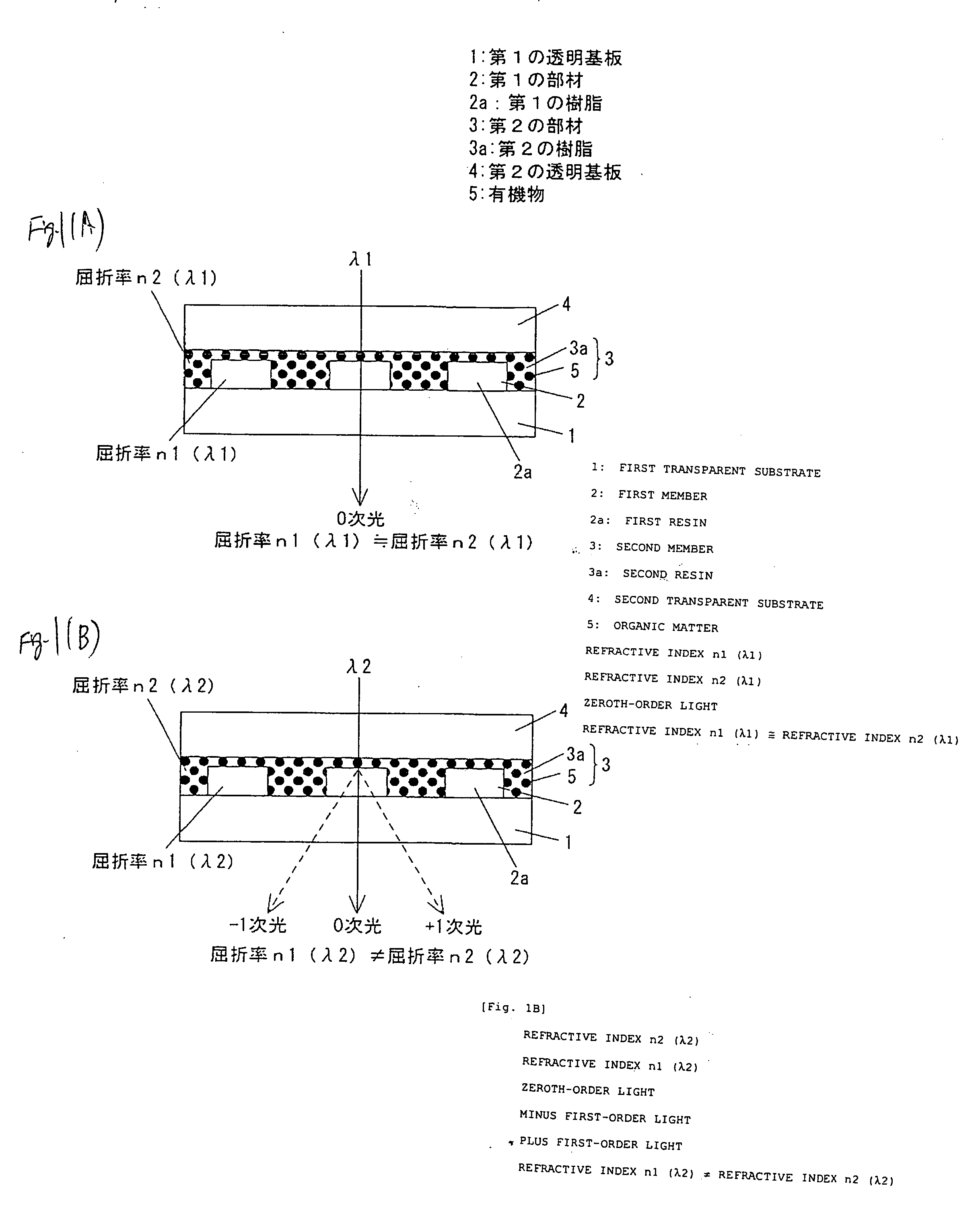
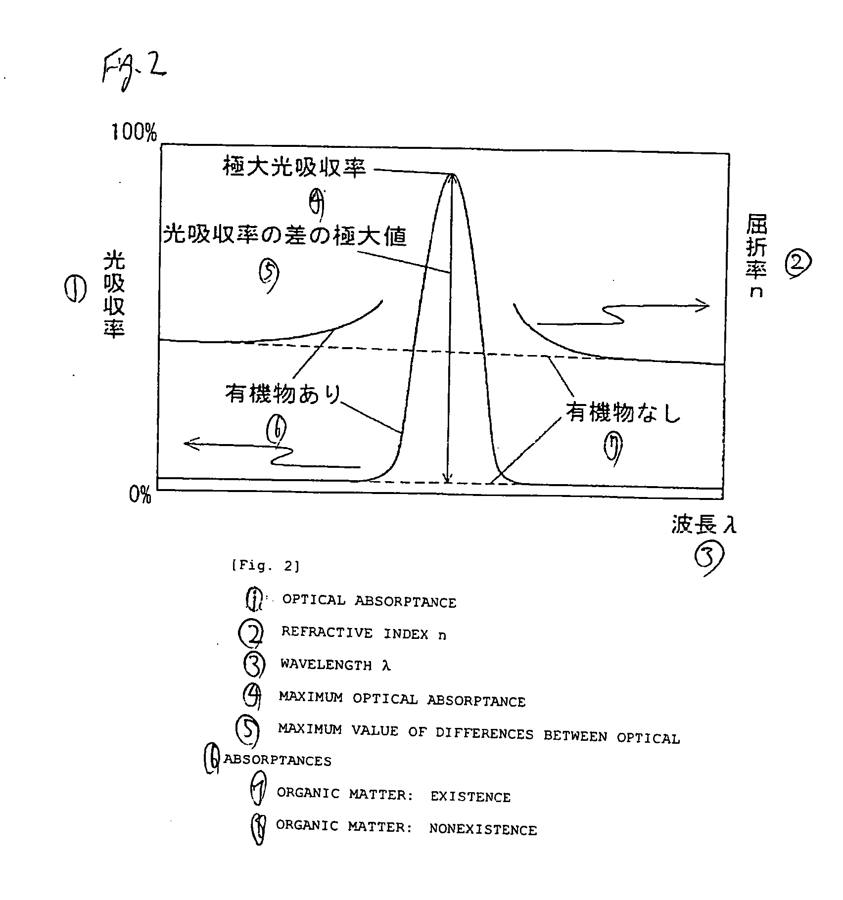
[0011] The second member transmits a wavelength λ1 of light for DVDs and a wavelength λ2 of light for CDs and dissolves an organic matter having optical absorption in a predetermined wavelength range at a molecular level. A dye of the organic matter has optical absorption in the wavelength of visible light. Accordingly, since the organic matter is dissolved at a molecular level in the second resin that is a solvent and thus incident light is dispersed, the transmittance in the wavelength λ1 and the wavelength λ2 can be increased.
[0014] Therefore, the diffractive element of the invention has a high transmittance in the wavelength λ1 and the wavelength λ2, and can transmit either the wavelength λ1 of light or the wavelength λ2 of light, and diffract and split the other wavelength of light. Since the optical pickup device equipped with the diffractive element of the invention has a high transmittance in the wavelength λ1 and the wavelength λ2, and can increase the output of laser light to be radiated onto an optical disc, it can meet attainment of a high speed. Therefore, the optical disc apparatus equipped with the optical pickup device can also meet attainment of a high speed.

Problems solved by technology

Therefore, it is difficult to increase the transmittance of the second member including an organic pigment, in the wavelength λ1 of light for DVDs and the wavelength λ2 of light for CDs.
Therefore, the light for DVDs and CDs which transmits through the diffractive element may be lost.

Method used


Image

  • Diffractive element, method of manufacturing the same, optical pickup device, and optical disc apparatus
  • Diffractive element, method of manufacturing the same, optical pickup device, and optical disc apparatus
  • Diffractive element, method of manufacturing the same, optical pickup device, and optical disc apparatus

Examples


embodiment 1

[0087] Embodiment 1 of the invention will be described referring to the accompanying drawings.

[0088] First, the structure will be described. FIG. 1 shows the structure of a diffractive element of Embodiment 1 of the invention. FIG. 1A shows that a wavelength λ1 of light transmits through the diffractive element, and FIG. 1B shows that a wavelength λ2 of light transmits through the diffractive element. The diffractive element is configured such that a first member 2 and a second member 3 which constitutes a diffraction grating are sandwiched between a first transparent substrate 1 and a second transparent substrate 4. Two wavelengths of light from a light source enter the diffractive element of the invention. The diffractive element has a function of allowing one wavelength of light to be transmitted therethrough and the other wavelength of light to be separated and emitted to an optical disc. The diffraction grating causes a diffraction phenomenon by alternately and appropriately a...

embodiment 2

[0104] Embodiment 2 of the invention will be described referring to the accompanying drawings. FIG. 6 shows the procedure of fabricating a diffractive element of Embodiment 2. FIG. 6A shows a first transparent substrate, FIG. 6B shows that a second member has been coated and cured on the first transparent substrate, FIG. 6C shows that the coated second member is irradiated with ultraviolet rays through a mask pattern, FIG. 6D shows that irregular shapes have been made in the second member, FIG. 6E shows that a first member has been filled, and FIG. 6F shows that the first member has been cured by keeping a second transparent substrate under heating after the second transparent substrate is superimposed on the first member. In Embodiment 2, irregular shapes are physically formed in a second resin 3a having a dissolved organic matter 5 to make a diffraction grating.

[0105] In Embodiment 2, a first transparent substrate 1 and a second transparent substrate 4 are the same as those in Em...

embodiment 3

[0109] Embodiment 3 of the invention will be described referring to the accompanying drawings. FIG. 7 shows the procedure of fabricating a diffractive element of Embodiment 3. FIG. 7A shows a second resin having a dissolved organic matter, FIG. 7B shows a first transparent substrate, FIG. 7C shows that a second member has been coated and cured on the first transparent substrate, FIG. 7D shows that the coated second member is irradiated with ultraviolet rays through a mask pattern, and FIG. 7E shows that a diffraction grating has been formed by radiation / non-radiation of ultraviolet rays. In Embodiment 3, a diffraction grating is formed without forming physical irregular shapes, unlike in Embodiment 1 and Embodiment 2.

[0110] In Embodiment 3, a first transparent substrate 1 is the same as that in Embodiment 1, and thus the description thereof will be incorporated herein. As the second resin 3a, there were used, epoxy-based thermosetting adhesives, such as 310, 320 and 330 of Epo-Tek ...


PUM


Abstract

There is provided a diffractive element including a first member 2, which includes a first resin 2a and has a predetermined refractive index, and a second member 3, which has the same refractive index as the first member 2 having the predetermined refractive index in one wavelength of light and has a refractive index different from the first member 2 having the predetermined refractive index in the other wavelength of light. The first member 2 and the second member 3 are alternately arranged within an incidence plane of the two wavelengths of light, thereby constituting a diffraction grating. The second member 3 includes a second resin 3a to dissolve an organic matter 5 having optical absorption in a predetermined wavelength range at a molecular level, whereby the refractive index of the second member 3 is formed.

Description

BACKGROUND OF THE INVENTION [0001] 1. Field of the Invention [0002] The present invention relates to a diffractive element which selectively diffract different wavelengths, to a method of manufacturing the diffractive element, and to an optical pickup device and an optical disc apparatus, which are equipped with the diffractive element. [0003] 2. Description of the Related Art [0004] Conventionally, in digital versatile discs (DVDs), recording or reproducing of information is performed by a wavelength λ1 (about 650 nm) of laser light. On the other hand, in compact discs (CDs), recording or reproducing of information is performed by a wavelength λ2 (about 780 nm) of laser light. In optical disc apparatuses which perform recording or reproducing on these two types of discs, a dual-wavelength laser light source which emits two wavelengths of laser light has been used. Diffractive elements with wavelength selectivity which transmit the wavelength λ1 of light for DVDs without any change ...

Claims


Application Information

Patent Timeline
IPC IPC(8): G02B27/42G11B11/00G02B5/18
CPCG02B27/42G02B27/4238G02B27/4261G02B27/4277G02B27/4294G11B7/1275G11B7/1353G11B2007/0006
Inventor MINODA, TAKATOSHISEKI, NORIAKIONO, EIZO
Owner PANASONIC CORP
Learn More