
Projection optical system and exposure apparatus having the same

a technology of projection optical system and exposure apparatus, which is applied in the direction of photomechanical treatment, printing, instruments, etc., can solve the problems of lowering transfer accuracy and yield, deteriorating line width control, and inability to meet the demand for high-quality exposure, etc., and achieves high resolution and high-quality exposure

Inactive Publication Date: 2006-08-10
CANON KK
View PDF15 Cites 55 Cited by
  • Summary
  • Abstract
  • Description
  • Claims
  • Application Information

AI Technical Summary

Benefits of technology

[0006] Accordingly, the present invention is directed to a projection optical system and an exposure apparatus having the same, which can achieve a high-quality exposure and a high resolution.

Problems solved by technology

A long-range flare in the projection optical system is one of the factors that deteriorates the line width control.
The air bubble shields the exposure light, results in lowered transfer accuracy and yield, and cannot satisfy the demand for the high-quality exposure.
If Japanese Patent Applications, Publication Nos. 2003-017396 and 2001-264626 are ordinarily applied to the immersion exposure, the light-shielding part becomes an influence that causes a mixture of the air bubble to the liquid, and the high-quality exposure cannot be achieved.
In addition, the light-shielding part provided between the wafer and the projection optical system and a mechanism that supports and drives it intercept an optical path of a focal sensor for the wafer, or an arrangement of a focal detecting system is difficult in a usually dry system exposure apparatus.
Therefore, if a focal control is inadequate, the high-quality exposure cannot be executed.

Method used


Image

  • Projection optical system and exposure apparatus having the same
  • Projection optical system and exposure apparatus having the same
  • Projection optical system and exposure apparatus having the same

Examples


Embodiment Construction

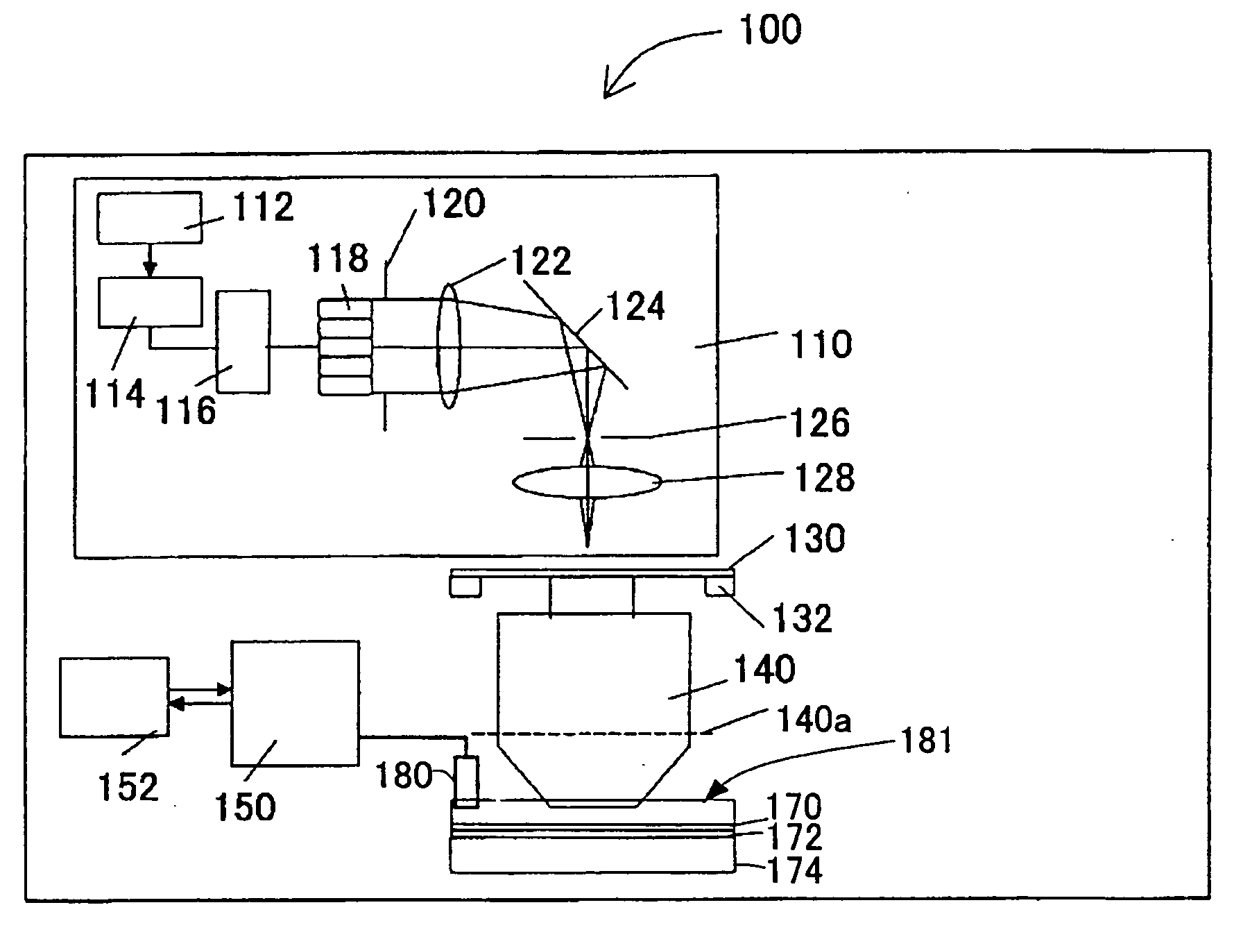
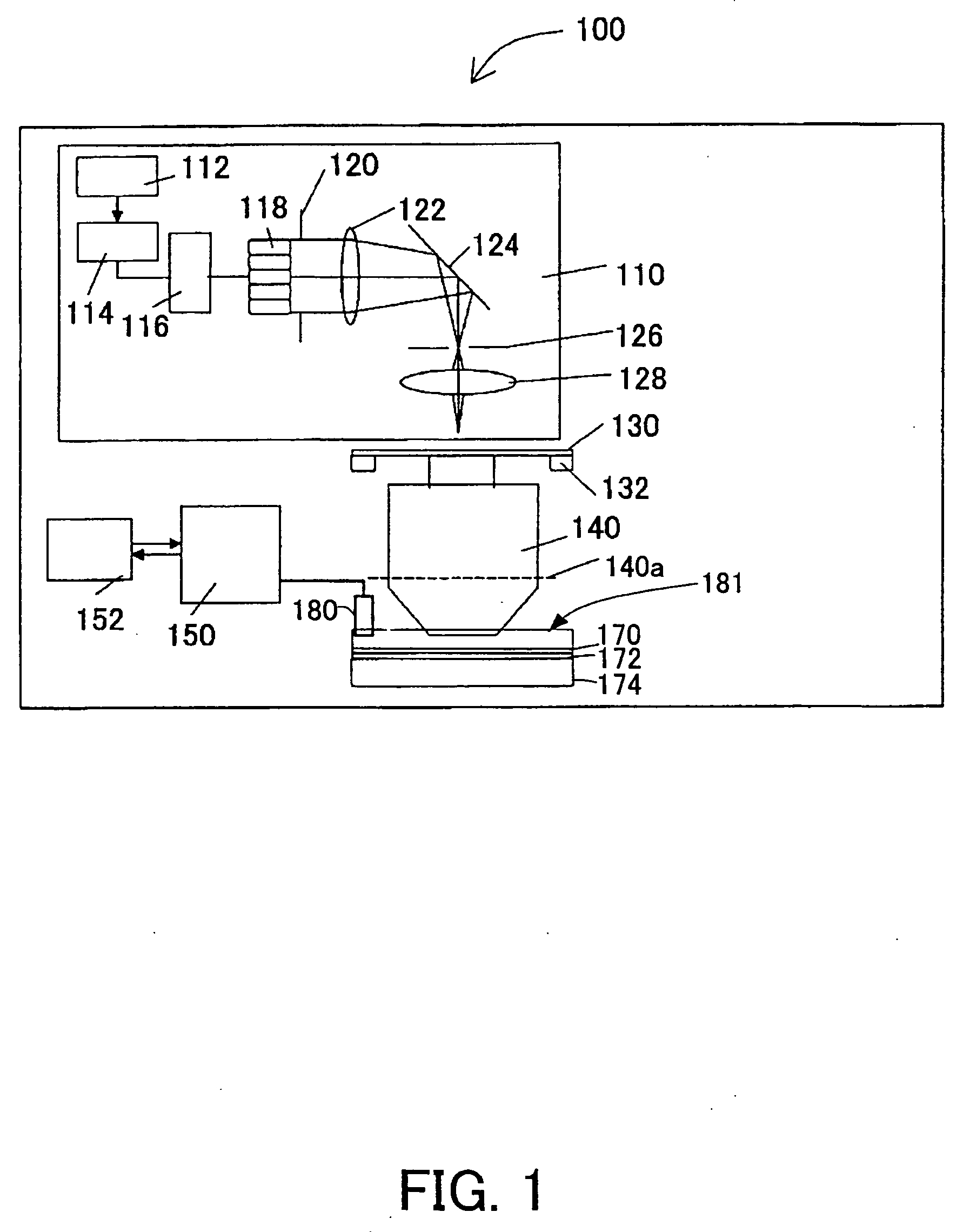
[0022] With reference to the accompanying drawings, a description will be given of an exposure apparatus 100 as one aspect according to the present invention. Here, FIG. 1 is a schematic block diagram of the exposure apparatus 100. The exposure apparatus 100 includes, as shown in FIG. 1, an illumination apparatus 110, a mask (reticle) 130, a mask stage 132, a projection optical system 140, a main controller unit 150, a monitor and input unit 152, a wafer 170, a retainer 172, a wafer stage 174, and a supply and recovery mechanism 180 that supplies and recovers a liquid 181 as an immersion material. The exposure apparatus 100 is an immersion type exposure apparatus that partially or entirely immerses the final surface of the final optical element in the projection optical system 140 at the wafer 170 side, and exposes a pattern on the mask 130 onto the wafer via the liquid 181. While the exposure apparatus 100 of the instant embodiment is a projection exposure apparatus in a step-and-s...


PUM


Abstract

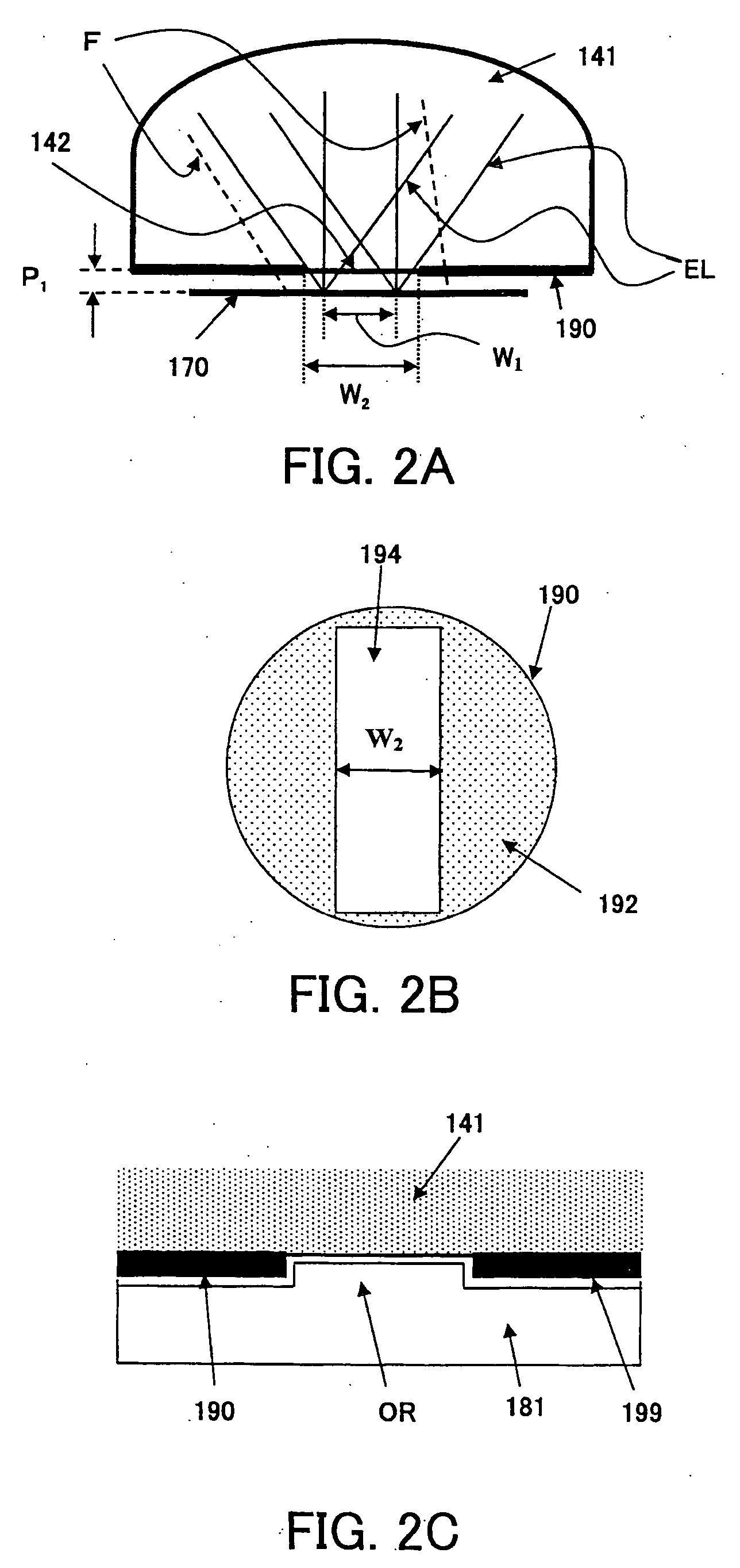
A projection optical system for projecting a pattern of a first object onto a second object. The projection optical system includes a field stop provided to an optical element in the projection optical system, which is closest to the second object. The field stop is provided for shielding the outside of a pattern projected area on the second object.

Description

BACKGROUND OF THE INVENTION [0001] The present invention relates generally to a projection optical system and an exposure apparatus having the same, and more particularly, to a structure of an optical element in the projection optical system, which is closest to an object. The present invention is suitable, for example, for a projection optical system used for an immersion exposure apparatus for exposing an object through the projection optical system and a liquid (fluid) between the projection optical system and the object. [0002] A projection exposure apparatus has been conventionally used to transfer a circuit pattern on a mask (or reticle) via a projection optical system onto a wafer, etc., and high-quality exposure at a high resolution has recently been increasingly demanded. [0003] The immersion exposure has attracted attention as one means that satisfies this demand. See, for example, Japanese Patent Application, Publication No. 10-303114. The immersion exposure promotes the ...

Claims


Application Information

Patent Timeline
IPC IPC(8): G03B27/54
CPCG03F7/70341G03F7/70941
Inventor SEKINE, YOSHIYUKI
Owner CANON KK
Learn More