
Object editing system, object editing method and object editing program product

a technology for object editing and object editing, applied in the field of object editing system, object editing method and object editing program product, can solve the problems of affecting the smooth movement of objects, and reducing the number of snap functions so as to improve user operability and reduce the number of snap functions. operation that must be performed to move objects. the effect of smooth movement of objects

Inactive Publication Date: 2006-08-10
IBM CORP
View PDF5 Cites 105 Cited by
  • Summary
  • Abstract
  • Description
  • Claims
  • Application Information

AI Technical Summary

Benefits of technology

[0012] Therefore, in view of these problems, the present invention has been provided. It is an object of the present invention to provide a snap function for realizing a smooth movement of an object without deteriorating the operationality, to increase an editing efficiency of the object, and to improve usability.
[0016] The restriction means may inhibit the object from snapping the snap target present on the side opposite to the direction in which the object is moving.
[0019] The display area is a two-dimensional display area defined by a vertical axis and a horizontal axis. The restriction means may inhibit the snap references that are present on the side opposite to a vertical component of the direction in which the object is moving from snapping the snap target, or inhibit the snap references that are present on the side opposite to a horizontal component of the direction in which the object is moving from snapping the snap target.
[0020] The display area is a two-dimensional display area defined by a vertical axis and a horizontal axis. The restriction means may inhibit the snap references that are present on the side opposite to a vertical component of the direction in which the object is moving from snapping the snap target, and inhibit the snap references that are present on the side opposite to a horizontal component of the direction in which the object is moving from snapping the snap target.
[0035] According to the present invention, the number of snap function operations that must be performed to move an object can be reduced, and the smooth movement of the object can be achieved without deteriorating user operability. As a result, the efficiency of object editing is increased, and usability is improved.

Problems solved by technology

When the interval between grids used as references is short, or when many other objects are present, the snap function must perform more work than necessary to move a specific object to a desired location, and therefore moving the object smoothly may be difficult.
As described above, when the conventional snap function is employed, the function must perform more work than necessary to move a specific object to a desired location, and this hinders the smooth movement of the object.
According to the technology disclosed in Japanese Patent Laid-Open Publication No. 2001-281835, while it is possible to suppress unnecessary snaps caused when moving an object to some extent, only a snap point closest to a mouse cursor is in a snappable condition out of four snap points of the object and therefore there is a limit in the number of snap points in the snappable condition, thereby deteriorating the operationality problematically.
Moreover, in the conventional snap function, there has also been known a technology of inhibiting the snap function from being operated unnecessarily by temporarily invalidating the snap function with a combination of a drag-and-drop operation with a mouse and a keyboard operation, in other words, with a depression of a shift key or the like on a keyboard at the time of the drag-and-drop operation.
These functions, however, require simultaneous processing of a plurality of operations such as the combination of the drag-and-drop operation and the keyboard operation, which necessarily requires operations with both hands and thereby deteriorates the operationality.
Furthermore, it has been hard for a user to find the operation method of the combined plurality of operations and to learn the operation method.
Due to these circumstances, the foregoing conventional snap functions cannot move the object smoothly without deteriorating the operationality, thereby hindering an improvement in usability in object editing of an electronic document.

Method used


Image

  • Object editing system, object editing method and object editing program product
  • Object editing system, object editing method and object editing program product
  • Object editing system, object editing method and object editing program product

Examples


Embodiment Construction

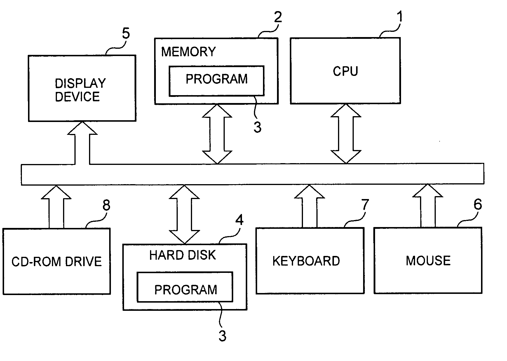
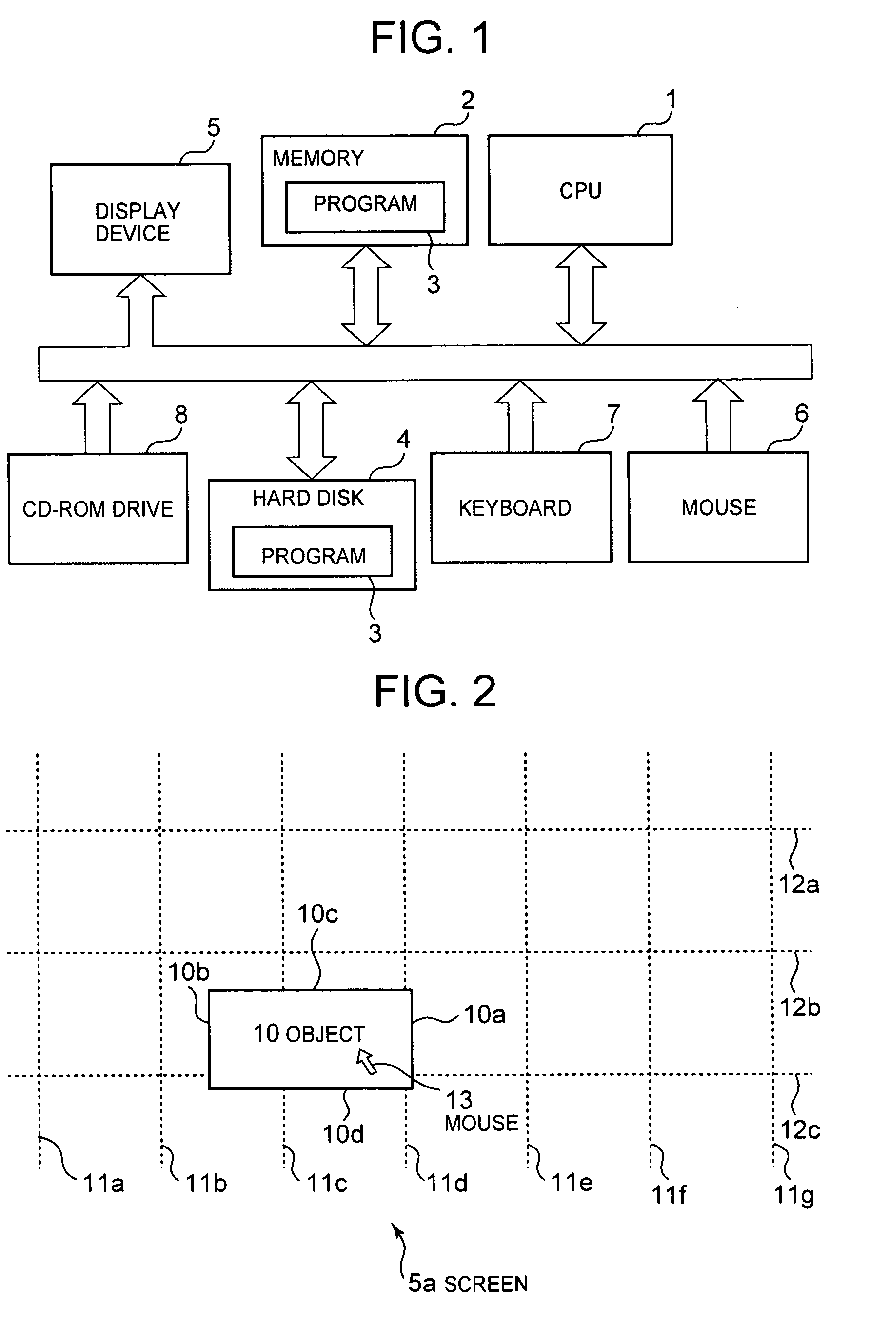
[0046] An embodiment of the present invention will now be specifically described while referring to FIG. 1. FIG. 1 is a schematic diagram showing the configuration of an object editing system according to an embodiment of the invention. The object editing system in this embodiment includes a central processing unit (CPU) 1, a memory 2, an object editing program 3, a hard disk 4, a display device 5, a mouse 6, a keyboard 7 and a CD-ROM drive 8.

[0047] The CPU 1 is a device for executing the object editing program 3. The memory 2 is a storage device into which the object editing program 3, which is stored on the hard disk 4, is temporarily loaded for execution. The mouse 6 and the keyboard 7 are data input devices a user employs when inputting commands to be executed by the CPU 1, or when using the object editing program 3. The CD-ROM drive 8 is a device used, in accordance with a command issued by the CPU 1, to transfer the object editing program 3, stored on a CD-ROM, to the hard di...


PUM


Abstract

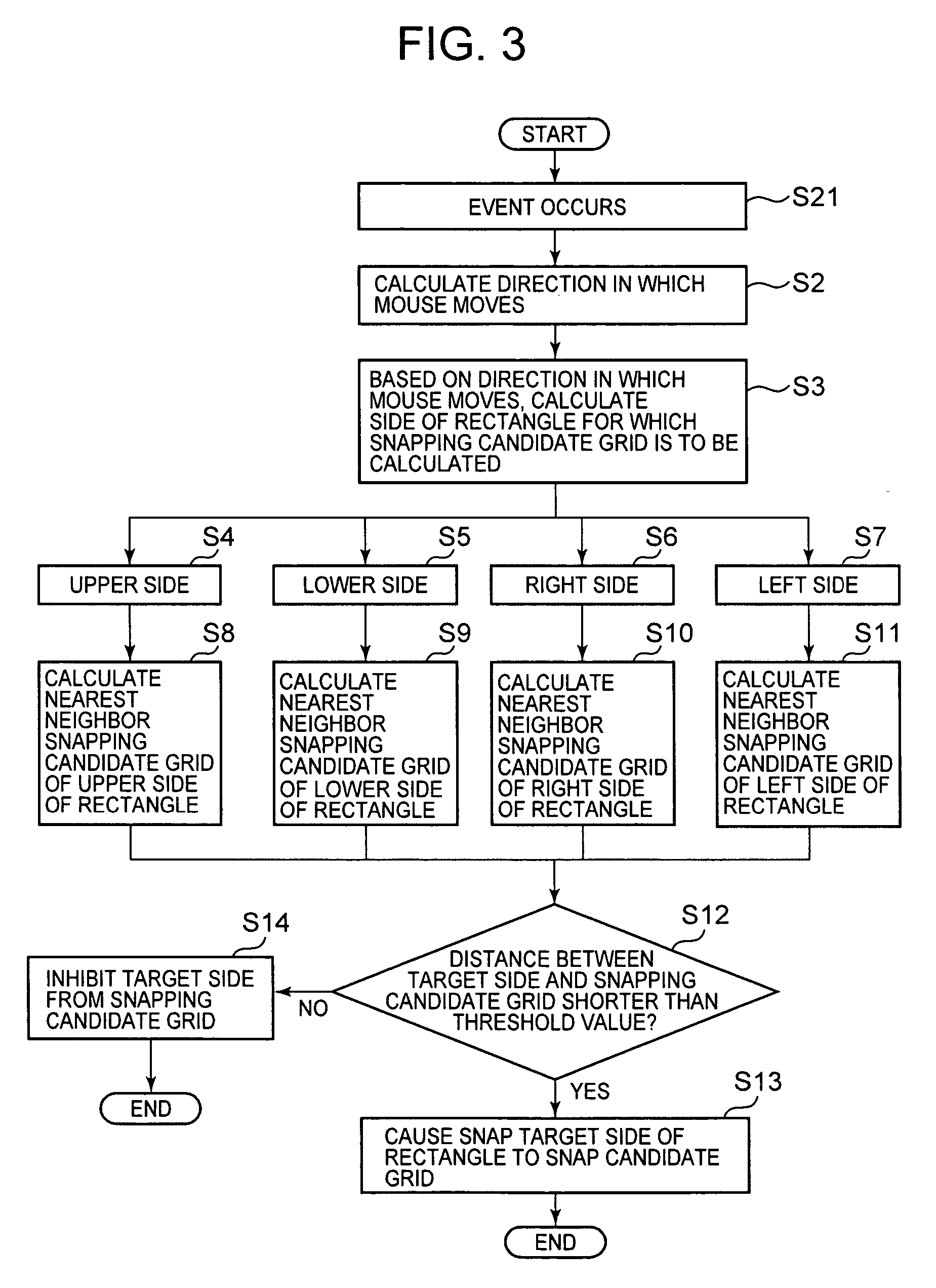
The present invention provides a snap function that can move an object smoothly, without deteriorating the user operability. According to the present invention, there is provided an object editing system, including: an arrangement system for arranging an object and a snap target in a given display area; a moving system for moving the object in the display area; a snap system for causing the object to snap the snap target on a basis of a distance between the object and the snap target; and a restriction system for inhibiting the object from snapping the snap target on a basis of a direction in which the object is moving. According to the object editing system of the invention, the snap system causes the object to snap the snap target once the distance between the object and the snap target has become smaller than a predetermined threshold value.

Description

FIELD OF THE INVENTION [0001] The present invention relates to a technique for using a computer to edit electronic documents. Particularly, the present invention relates to a system for editing objects in electronic documents, an object editing method and an object editing program product. BACKGROUND OF THE INVENTION [0002] When computers are employed for the layout editing of electronic documents, object snap functions are frequently used by electronic document layout editing tools to position objects at desired locations. When, for example, an object is continuously selected by means of a mouse and is moved (dragged) to a desired grid, the snap function aids in the object's being automatically arranged on a grid in a work area or on another object. [0003] An electronic document layout editing screen is shown in FIG. 8. A plurality of vertical grids 101a to 101e and horizontal grids 102a to 102c are arranged on a screen 103. In the state shown in FIG. 8, a snap function has been us...

Claims


Application Information

Patent Timeline
Patent Type & Authority Applications(United States)
IPC IPC(8): E04B1/62G06F3/048G06F3/0487
CPCG06F3/04845
Inventor KINOSHITA, SATOKOMIURA, KEIJISHIBATA, EIKI
Owner IBM CORP
Learn More