
Ocular prosthesis and fabrication method of same

a technology of ocular prosthesis and fabrication method, which is applied in the field of ocular prosthesis, can solve the problems of lack of high degree of precision, time-consuming, and outdated technology of the current fabrication method

Active Publication Date: 2006-08-03
MR TIMOTHY P FRIEL
View PDF38 Cites 29 Cited by
  • Summary
  • Abstract
  • Description
  • Claims
  • Application Information

AI Technical Summary

Problems solved by technology

Although several improvements have been reported in the general art of ocular prosthesis, fabrication methods currently used are based upon outdated technology, are cumbersome, lack a high degree of precision, and are time consuming, as further explained below.
However, despite the above-noted exemplary improvements, conventional fabrication methods produce ocular prosthetics whose shapes are usually inaccurate and difficult to reproduce, are time consuming, employ materials and methods of curing the materials that have the potential to cause undesirable allergic reactions, and are labor intensive.
Because of the empirical nature of this portion of the conventional fabrication processes, an undesirable variation in the accuracy of the shape occurs.
The problems associated with hand painted irises include the inherent inaccuracy of hand painting and the fact that only a limited three-dimensional depth effect can be portrayed.
Because the amount of undesirable monomers that may remain in the prosthesis, the curing process requires long curing times. It is also not practical to destructively test the material once cured in order to ensure proper polymerization as the batch size is necessarily small, then the prosthesis itself would be destroyed.

Method used


Image

  • Ocular prosthesis and fabrication method of same
  • Ocular prosthesis and fabrication method of same
  • Ocular prosthesis and fabrication method of same

Examples


first embodiment

[0041]FIG. 5 is a flowchart illustrating a first embodiment for an ocular prosthesis fabrication method according to the invention. As illustrated, an impression of the anophthalmic or enophthalmic socket at 300 or a patient's existing ocular prosthesis at 310 is provided and placed into a three dimensional scanning device at 320.

[0042] The impression taken of the patient's anophthalmic or enophthalmic socket is done in a manner that is well known to an ocularist, as already described. In summary, the process includes the placement of an impression tray (similar to a dental impression tray, but of an appropriate shape for the ocular socket) into the patient's orbit and injecting an alginate, Polyvinylsiloxane, or other dental type impression material into the socket. This material forms in a short period of time into a semi rigid shape that has the contours of the ocular socket and is then removed from the socket. This process of obtaining an impression has previously been described...

second embodiment

[0047] A second embodiment for the ocular prosthesis fabrication method according to the invention, which includes the manipulation and printing of an iris image at 410, is illustrated in FIG. 6. As shown, an impression of the eye socket and at least one photograph of the patient's remaining eye, or a “donor” iris photograph of desirable character in the case of bilaterally blind patients, are first provided at 400. Subsequently, in one hand, the impression or the previous well fitting prosthesis is scanned three dimensionally at 420, the scanned data are manipulated at 430, and the white and clear parts of the prosthesis are machined at 440, and, on the other hand, the photograph of the patient's remaining eye is manipulated and an iris to be disposed on the final ocular prosthesis is then produced at 410. At step 450, the iris produced at 410 is added to the white and clear parts produced at 440; and the sclera is then modified. The parts are then combined at 460 and the final pro...


PUM

PropertyMeasurementUnit
coloraaaaaaaaaa
diameteraaaaaaaaaa
transparencyaaaaaaaaaa

Abstract

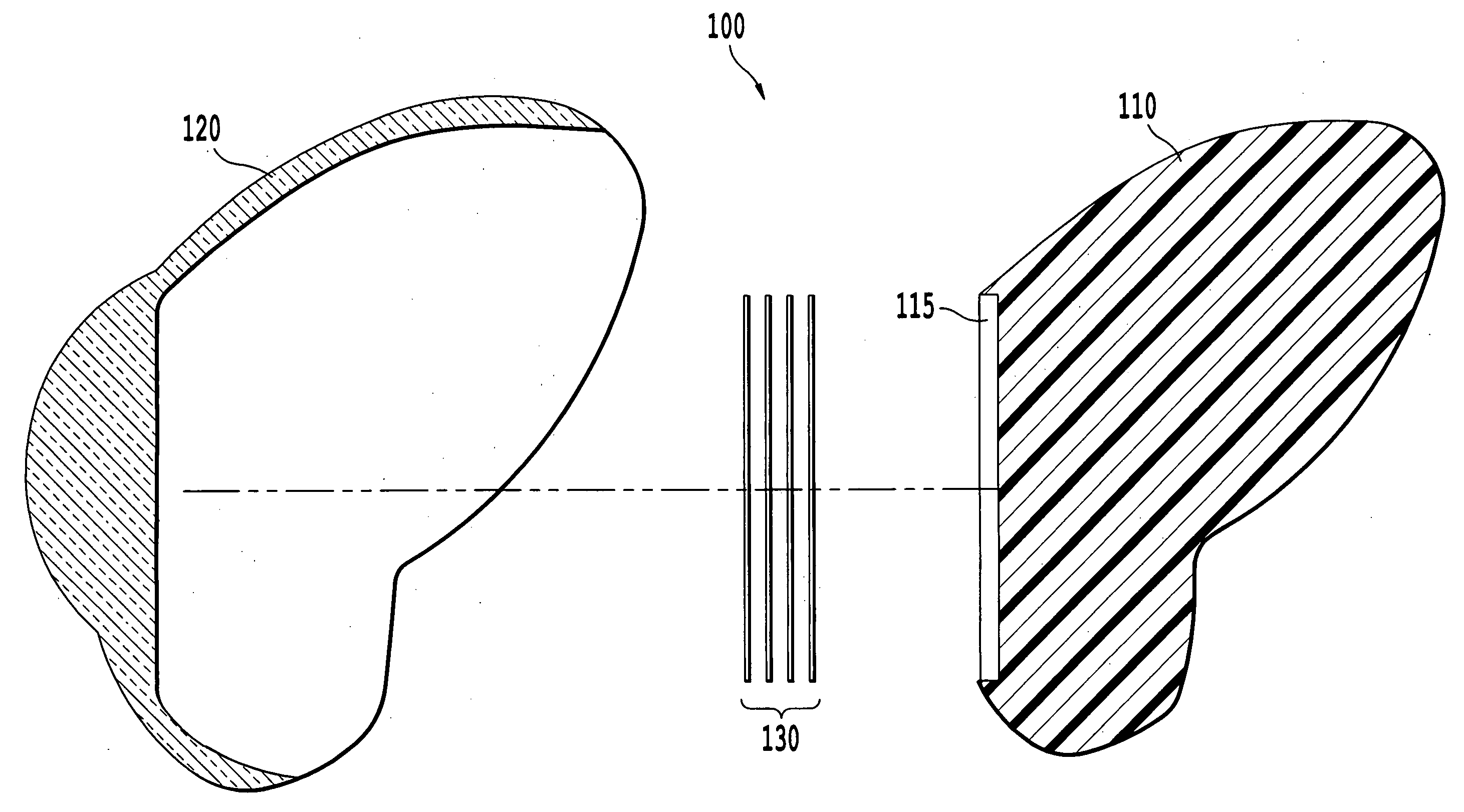
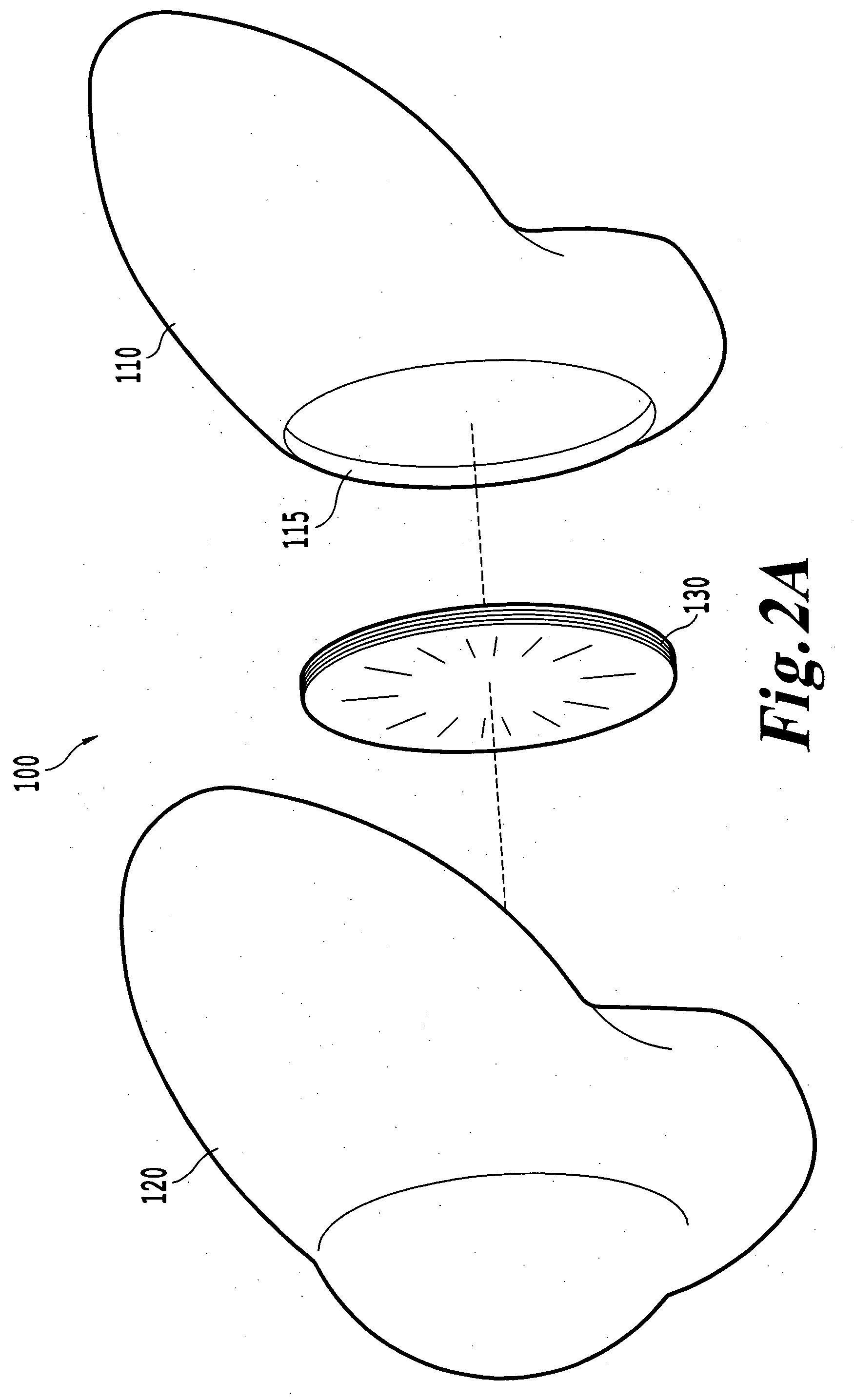
An ocular prosthesis includes a posterior sclera portion partially nested with an anterior clear portion. An iris disk piece and / or a retinal chip may also be disposed between the posterior and anterior portions. A method for manufacturing the ocular prosthesis includes scanning an impression of an eye socket or an existing ocular prosthesis, fabricating posterior and anterior portions from geometrical models generated from the scans, and forming the ocular prosthesis by joining the two portions. In another embodiment of the method, a photograph of an iris is provided and manipulated to form a multi disk iris piece to be used in the ocular prosthesis.

Description

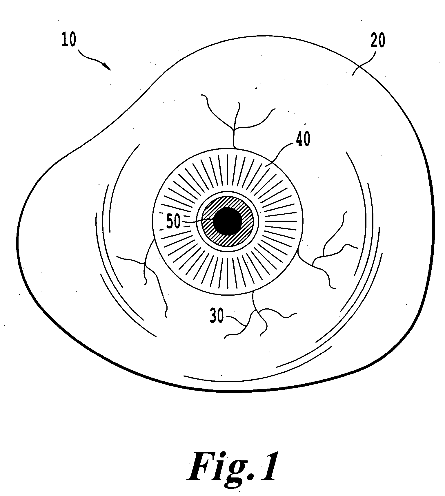
CROSS-REFERENCE TO RELATED APPLICATIONS [0001] This application claims the benefit of U.S. Provisional Application No. 60 / 649,020, filed on Feb. 1, 2005. The content of which is incorporated herein by reference in its entirety.BACKGROUND OF THE INVENTION [0002] 1. Field of the Invention [0003] The invention relates in general to a prosthetic eye and, more particularly, to an ocular prosthesis and a process of fabrication of the same. [0004] 2. Description of the Related Art [0005] It is not uncommon for a person to have a natural eye removed because of a severe trauma, a congenital abnormality, or a disease, such as, for example, an infection, the presence of a tumor, or untreatable painful glaucoma. In these situations, the natural eye is removed by an acceptable medical procedure, for example, by enucleation or evisceration, during which a orbital implant is surgically implanted to replace lost orbital volume. It is also not uncommon for a person to have a smaller than normal, or ...

Claims


Application Information

Patent Timeline
Patent Type & Authority Applications(United States)
IPC IPC(8): A61F2/14B29C35/08B29C41/02
CPCA61F2/0059A61F2/141A61F2250/0063B29C65/1406B29C65/4845B29C67/0051B29C66/545B29C67/0077B29C2035/0827B29L2011/0008A61F2240/002B29C65/48B29C66/5412B29C67/0059B29D11/02B33Y10/00B33Y50/00B33Y80/00B29C64/112B29C64/153
Inventor FRIEL, TIMOTHY P.
Owner MR TIMOTHY P FRIEL
Learn More