Fluorescence observation endoscope apparatus and fluorescence observation method
a fluorescence observation and endoscope technology, applied in the field of fluorescence observation endoscope apparatus and fluorescence observation method, can solve the problems of interference in observation and diagnosis based on observation and cannot be determined from fluorescence images
- Summary
- Abstract
- Description
- Claims
- Application Information
AI Technical Summary
Problems solved by technology
Method used
Image
Examples
first embodiment
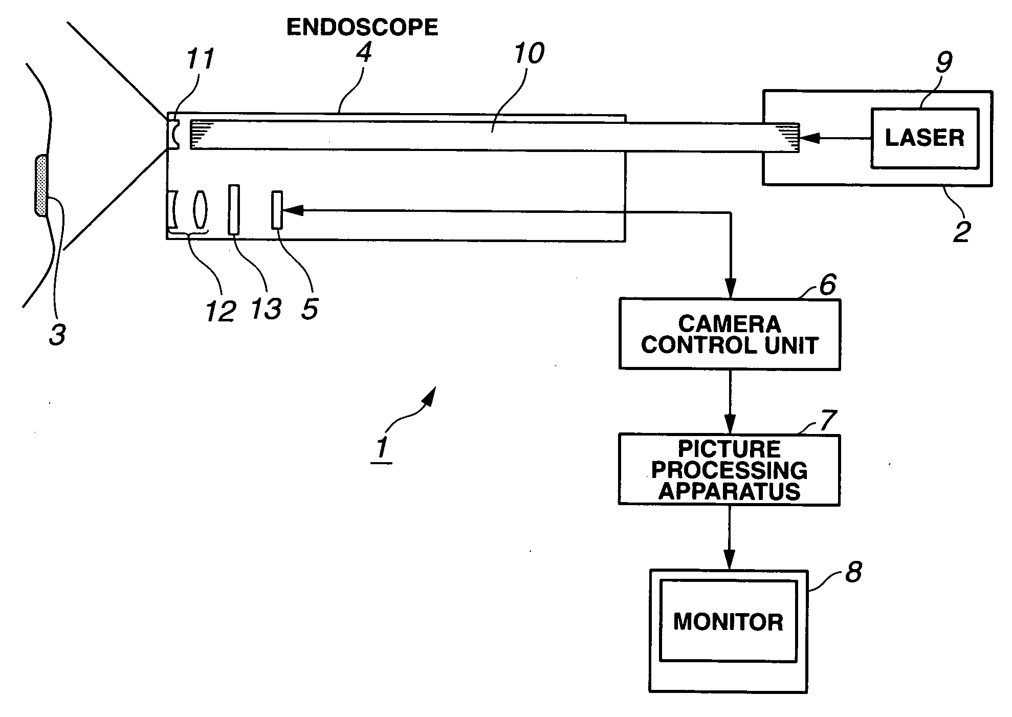
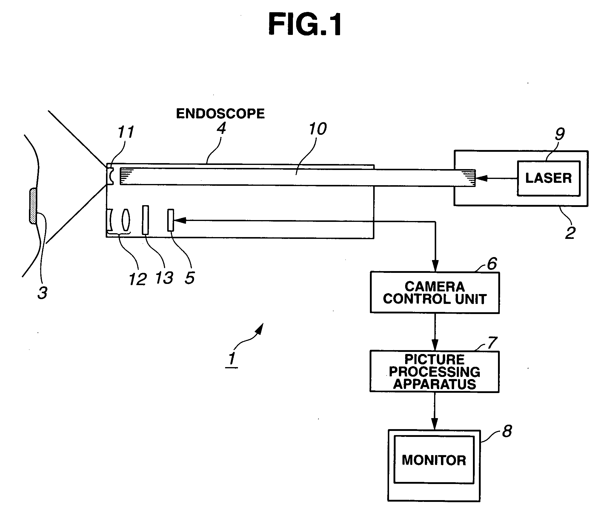
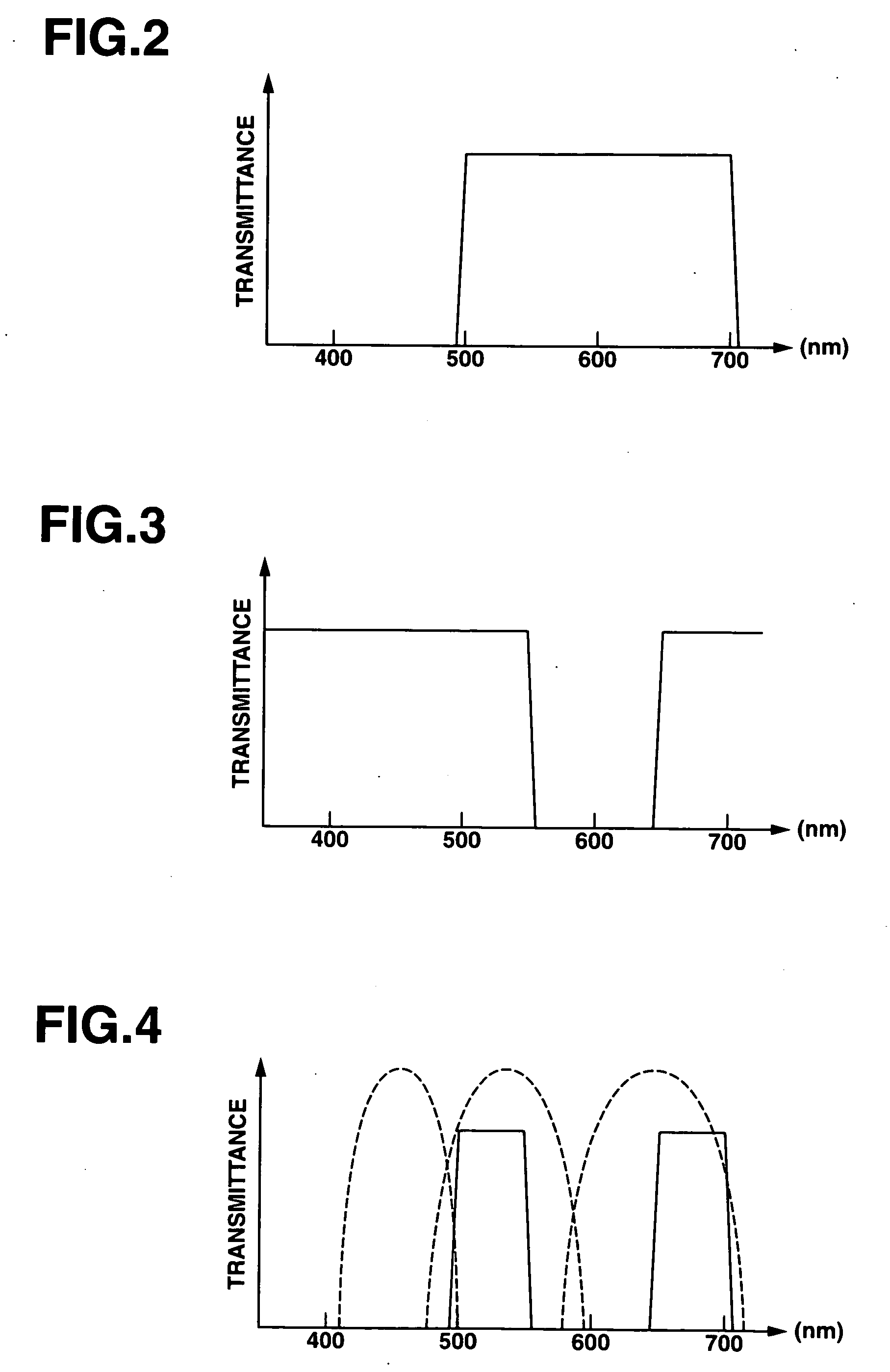
[0039]FIG. 1 to FIG. 11 relate to the first embodiment of the present invention. FIG. 1 is a configuration diagram showing the entire configuration of a fluorescence observation endoscope apparatus to diagnose a lesion site based on fluorescence. FIG. 2 is a characteristic diagram showing the transmission characteristic of an interference filter of a fluorescence filter shown in FIG. 1. FIG. 3 is a characteristic diagram showing the transmission characteristic of a color filter of the fluorescence filter shown in FIG. 1. FIG. 4 is a characteristic diagram showing the transmission characteristic of the fluorescence filter and the spectral characteristic of a color image pickup device shown in FIG. 1. FIG. 5 is a functional block diagram for explaining the functions of an image processing apparatus shown in FIG. 1. FIG. 6 is a flow chart for explaining the actions of the image processing apparatus shown in FIG. 5. FIG. 7 is a diagram for explaining the action of the region emergence n...
second embodiment
[0064]FIG. 12 to FIG. 16 relate to the second embodiment of the present invention. FIG. 12 shows the configuration of a fluorescence observation endoscope apparatus according to the second embodiment of the present invention. FIG. 13A to FIG. 13C show examples of fluorescence spectrum characteristics attained when excitation light is radiated to lesion sites and the like and fluorescence signal data by a fluorescence filter. FIG. 14 shows the configuration of an image processing apparatus. FIG. 15 shows the content of processing by a residue detection method according to the present embodiment. FIG. 16A shows the content of processing in which a residue is discriminated based on the fluorescence spectrum measurement result. FIG. 16B shows another example of a determination processing of steps S25 and S26 shown in FIG. 16A.
[0065] As shown in FIG. 12, a fluorescence observation endoscope apparatus 100 in the second embodiment of the present invention comprises an optical endoscope 10...
third embodiment
[0147] The third embodiment of the present invention will be described below with reference to FIG. 19 to FIG. 21. The same constituents as in the second embodiment are indicated by the same reference numerals as those set forth above and explanations thereof will not be provided. FIG. 19 shows the configuration of a fluorescence observation endoscope apparatus 100B according to the third embodiment of the present invention.
[0148] The fluorescence observation endoscope apparatus 100B shown in FIG. 19 comprises an electronic endoscope 102B to be inserted into a body cavity, a light source 103B to supply excitation light and illumination light for normal observation to a light guide 111 of this electronic endoscope 102B, an image processing apparatus 105B to conduct image processing of image pickup signal image-captured by the electronic endoscope 102B, and a monitor 106 to display an image processed by this image processing apparatus 105B.
[0149] The electronic endoscope 102B includ...
PUM
 Abstract
Description
Claims
Application Information
 - R&D
- Intellectual Property
- Life Sciences
- Materials
- Tech Scout
- Unparalleled Data Quality
- Higher Quality Content
- 60% Fewer Hallucinations
Browse by: Latest US Patents, China's latest patents, Technical Efficacy Thesaurus, Application Domain, Technology Topic, Popular Technical Reports.
© 2025 PatSnap. All rights reserved.Legal|Privacy policy|Modern Slavery Act Transparency Statement|Sitemap|About US| Contact US: help@patsnap.com


