
Electric double layer capacitor

a double-layer capacitor and capacitor technology, applied in the direction of electrolytic capacitors, dynamo-electric components, propulsion systems, etc., can solve the problems of high viscosity no high electric conductivity, etc., and achieve excellent characteristics, low resistance, and high resistance to voltage.

Inactive Publication Date: 2006-08-03
ASAHI GLASS CO LTD
View PDF7 Cites 7 Cited by
  • Summary
  • Abstract
  • Description
  • Claims
  • Application Information

AI Technical Summary

Benefits of technology

[0013] As described above, the electrolytic solution of the present invention has a low resistance and a high withstanding voltage, and exhibits excellent characteristics such as a low resistance and a high withstanding voltage even in a low temperature region. Accordingly, the electric double layer capacitor of the present invention comprising such an electrolytic solution has a high withstanding voltage and is excellent also in low temperature characteristics.

Problems solved by technology

However, such a solvent having a high dielectric constant, in which the electrolyte is highly soluble, usually has a high viscosity.
Therefore, although an electrolytic solution having a high electrolyte concentration will be obtained, no high electric conductivity will be obtained.
Further, a chain ether, a chain ester, a chain carbonate and the like, which are low viscosity solvents, have a low dielectric constant, whereby substantially no electrolyte will be dissolved therein, and no high electric conductivity will be obtained.
However, propylene carbonate may decompose when a voltage of about 2.9 V or higher is applied.
Further, electrochemically stable sulfolane has a high withstanding voltage and will not decompose by application of a voltage of up to about 3.4 V, but the electrolyte will hardly soluble in it, and it has a high melting point, and it is particularly poor in low temperature characteristics.
However, no sufficient solubility in a solvent having a low dielectric constant and a low viscosity has been achieved.

Method used


Image

  • Electric double layer capacitor
  • Electric double layer capacitor
  • Electric double layer capacitor

Examples


example 1

[0036] Ethanol was added to a mixture comprising a phenolic resin type activated carbon having a specific surface area of 2,000 m2 / g activated by steam, polytetrafluoroethylene and carbon black in a mass ratio of 8:1:1, and the mixture was kneaded and formed into a sheet. This was rolled in a thickness of 0.6 mm to obtain an electrode sheet, which was punched into disks having a diameter of 12 mm.

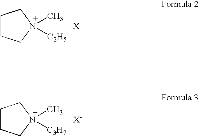
[0037] Such disk-shaped electrodes were bonded to the positive electrode side and negative electrode side insides, respectively, of a stainless steel casing serving as a current corrector and housing member for a coin-shaped cell by means of a graphite type conductive adhesive. Then, the entire assembly including the stainless steel casing was subjected to heat treatment under reduced pressure to remove water, etc. The electrodes were impregnated with an electrolytic solution having 2.0 mol / kg of EMPyBF4 dissolved in a solvent mixture comprising dimethyl carbonate, sulfolane and monofluoro...

example 2

[0038] A coin-shaped electric double layer capacitor was obtained in the same manner as in Example 1 except that as the electrolytic solution, a solution having 1.0 mol / kg of MPPyBF4 dissolved in a solvent mixture comprising dimethyl carbonate, sulfolane and monofluorobenzene in a mass ratio of 64:16:20, was used.


PUM


Abstract

To provide an electric double layer capacitor having a low resistance, a high withstanding voltage and an excellent low-temperature characteristic. This object is achieved by employing, for an electric double layer capacitor having a pair of polarized electrodes and an electrolytic solution capable of forming an electric double layer at the interface with the polarized electrodes, an electrolytic solution containing as an electrolyte a salt represented by the formula 1, and as solvents at least (1) a chain carbonate having at most 5 carbon atoms, (2) sulfolane or its derivative and (3) a fluorobenzene: herein each of R1 and R2 which are independent of each other, is a C1-4 alkyl group, and X− is an anion.

Description

TECHNICAL FIELD [0001] The present invention relates to an electric double layer capacitor. Particularly, it relates to an electric double layer capacitor having a low resistance, a high withstanding voltage and an excellent low-temperature characteristic. BACKGROUND ART [0002] As a shape of a conventional electric double layer capacitor, there may be a coin type wherein an element having a separator sandwiched between a pair of polarized electrodes composed mainly of activated carbon formed on current collectors, is accommodated together with an electrolytic solution in a metal casing, which is then sealed by a metal cover via a gasket, or a cylindrical type wherein an element having a pair of polarized sheet electrodes wound with a separator interposed therebetween, is accommodated together with an electrolytic solution in a metal casing, which is then sealed so that the electrolytic solution will not evaporate from an opening of the casing. [0003] Further, as one for a large curr...

Claims


Application Information

Patent Timeline
IPC IPC(8): H01G9/00G03F7/20H01G9/02H01G11/62H01L21/027H01L21/68H02K41/02H02K41/03
CPCH01G9/038H01G11/62Y02E60/13H01G11/60
Inventor KAWASATO, TAKESHIIKEDA, KATSUJIYOSHIDA, NAOKIHIRATSUKA, KAZUYA
Owner ASAHI GLASS CO LTD
Learn More