
Electrophoretic or bi-stable display device and driving method therefor

a display device and display device technology, applied in the direction of instruments, static indicating devices, etc., can solve the problem of insufficient pixels movemen

Inactive Publication Date: 2006-08-03
KONINKLIJKE PHILIPS ELECTRONICS NV
View PDF6 Cites 43 Cited by
  • Summary
  • Abstract
  • Description
  • Claims
  • Application Information

AI Technical Summary

Benefits of technology

The invention provides a drive circuit for a bi-stable display that reduces the non-zero average level of voltage across pixels. This is achieved by dividing the drive waveform into a sequence of sub-pulses with separation periods between them. The sub-pulses can have different energy levels to achieve the same optical transition. By controlling the number, duration, and separation period of the sub-pulses, the average energy level of the drive waveform can be minimized. This flexibility allows for a more efficient and consistent display.

Problems solved by technology

The optional shaking pulses have an energy which is large enough to change the optical state of the electrophoretic display but insufficient to move the pixels from one of the extreme optical states to the other.

Method used


Image

  • Electrophoretic or bi-stable display device and driving method therefor
  • Electrophoretic or bi-stable display device and driving method therefor
  • Electrophoretic or bi-stable display device and driving method therefor

Examples


Embodiment Construction

[0043] The indices i, j and k are used to indicate that of a particular item several are present or used. For example the pixel Pij indicates that any one of the pixels may be referred to, or the drive waveform DWk refers to any of the drive waveforms. On the other hand, DW1 refers to a particular one of the drive waveforms DWk.

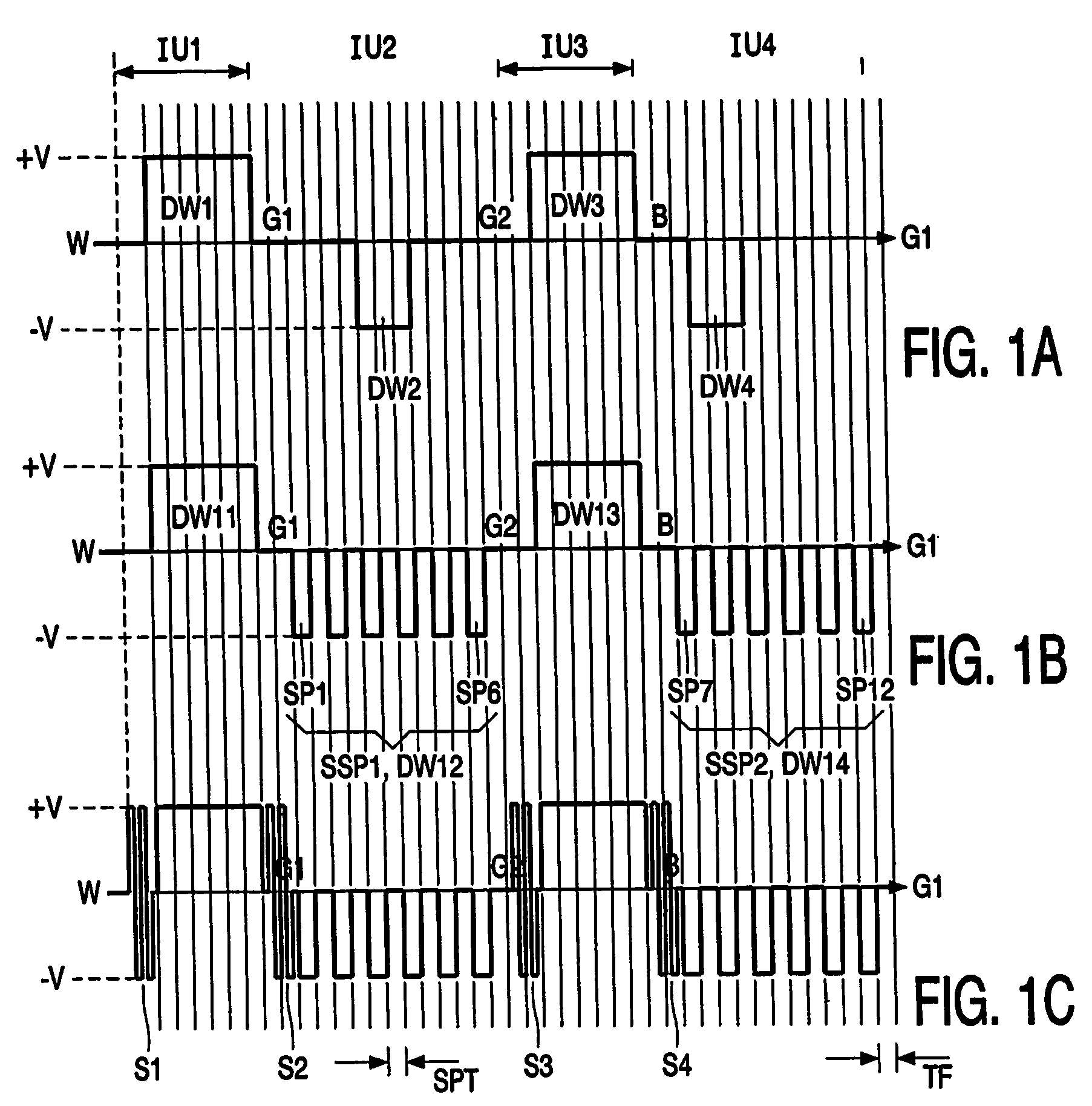
[0044]FIG. 1 shows drive waveforms to elucidate embodiments in accordance with the invention wherein a single drive pulse is replaced by a sequence of sub-pulses.

[0045] Intermediate levels (for example, grey if black and white particles are used in an EInk type display) in electrophoretic displays are difficult to generate reliably. In general, they are created by applying voltage pulses for specified time periods and thus are determined by the energy of the pulse applied. The intermediate levels are strongly influenced by image distortion, dwell time, temperature, humidity, lateral inhomogeneity of the electrophoretic foils etc. For example, in an EInk typ...


PUM


Abstract

A drive circuit for a bi-stable display comprises: a driver (101, 102) which supplies drive waveforms (DWk) to the pixels (Pij) of the display during an image update period (IUk) wherein the image presented by the pixels (Pij) is updated. A controller (103) controls the driver (101, 102) to supply, during the image update period (IUk) wherein a particular optical transition of a particular one of the pixels (Pij) is required, an associated one of the drive waveforms (DWk) to the particular one of the pixels (Pij). The associated one of the drive waveforms (DWk) comprises a sequence of a particular number of pulse, (SPk), wherein consecutive ones of the pulses (SPk) of the sequence are separated by a separation period of time (SPT). The particular number of said pulses (SPk), and / or a duration of said pulses (SPk), and / or a duration of the separation period (SPT) of the associated one of the drive waveforms (DWk) is determined to obtain the particular optical transition at a desired energy of the associated one of the drive waveforms (DWk) to decrease an average value of the associated one of the drive waveforms (DWk).

Description

FIELD OF THE INVENTION [0001] The invention relates to a drive circuit for a bi-stable display, to a method of driving a bi-stable display, and to a display apparatus comprising a bi-stable display and such a drive circuit. BACKGROUND OF THE INVENTION [0002] The publication “Drive waveforms for active matrix electrophoretic displays”, by Robert Zhener, Karl Amundson, Ara Knaian, Ben Zion, Mark Johnson, Guofu Zhou, SID2003 digest pages 842-845 discloses that grey scales are obtained in an electrophoretic display by modulating the pulse width and / or amplitude of a single drive pulse in each image update period wherein the image on the matrix display is refreshed. [0003] Generally, the average level of the voltage of the drive waveform for a particular pixel during a sequence of successive image update periods will not be zero. A non-zero average level across a pixel may degrade the pixel. SUMMARY OF THE INVENTION [0004] It is an object of the invention to provide a drive circuit for a...

Claims


Application Information

Patent Timeline
Patent Type & Authority Applications(United States)
IPC IPC(8): G09G3/34G09G3/20
CPCG09G3/2018G09G3/344G09G2300/08G09G2300/0876G09G2310/06G09G2320/0204G09G2320/0257G09G2330/04
Inventor ZHOU, GUOFUJOHNSON, MARK THOMAS
Owner KONINKLIJKE PHILIPS ELECTRONICS NV
Learn More