
Inflatable mailer, apparatus and method for preparing the same

Inactive Publication Date: 2006-08-03
SEALED AIR U S
View PDF52 Cites 42 Cited by
  • Summary
  • Abstract
  • Description
  • Claims
  • Application Information

AI Technical Summary

Benefits of technology

[0011] The invention also includes an apparatus for inflating the mailer. In one embodiment of the invention, the apparatus includes a conveying mechanism for conveying an inflatable mailer along a longitudinal pathway. The longitudinal pathway includes a nip through which the inflatable mailer is driven. Preferably, the inflatable mailer is positioned on the conveying mechanism so that the common channel is disposed at the trailing edge of the mailer as it passes between the nip. Passage of the inflatable mailer through the nip moves the controlled volume of gas from the inflatable chambers and into the common channel thereby causing the channel to inflate. The inflated channel forms an expanded space within the liner. An inflation needle then punctures the pouch and enters the now inflated common channel. Gas is introduced into the channel via the inflation needle. A sealing device seals the liner closed to prevent gas from escaping after the liner has been inflated to a desired level.
[0013] The inflatable liner provides an effective method of preparing a shipping container that can be easily inflated and used at a point of packaging. The inflatable mailers typically occupy less volume than conventional packaging materials resulting in possible savings in transportation costs and a reduction in the amount of space that is typically required for storage. Thus, the invention provides an inflatable mailer and device for inflating the same that overcomes many of the disadvantages that are associated with conventional packaging materials.

Problems solved by technology

The volume of gas in the inflatable liner is sufficient to inflate the common channel when the gas is moved from the inflatable chambers into the common channel, but when dispersed, the gas volume is not sufficient to inflate the liner to an appreciable extent.

Method used


Image

  • Inflatable mailer, apparatus and method for preparing the same
  • Inflatable mailer, apparatus and method for preparing the same
  • Inflatable mailer, apparatus and method for preparing the same

Examples


Embodiment Construction

[0028] The present invention now will be described more fully hereinafter with reference to the accompanying drawings, in which some, but not all embodiments of the inventions are shown. Indeed, the invention may be embodied in many different forms and should not be construed as limited to the embodiments set forth herein; rather, these embodiments are provided so that this disclosure will satisfy applicable legal requirements. Like numbers refer to like elements throughout.

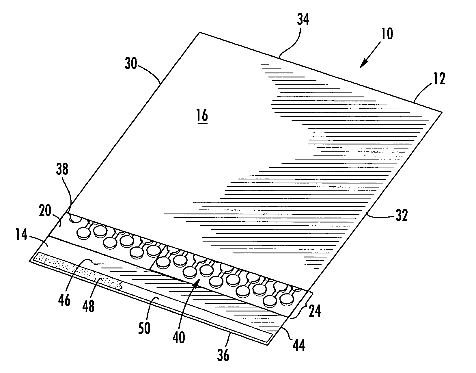
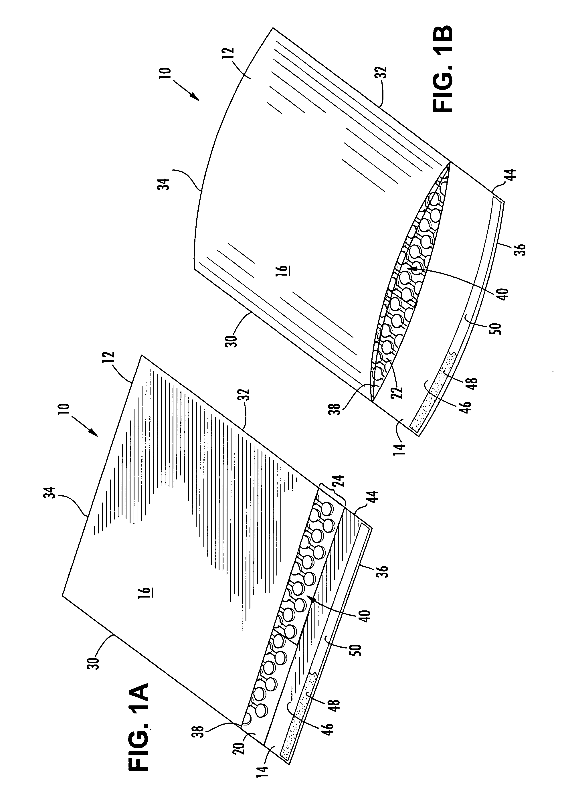
[0029] With reference to FIGS. 1A and 1B, an inflatable mailer in accordance with the invention is illustrated and broadly designated as reference number 10. As shown in FIG. 1A, the inflatable mailer comprises a pouch 12 having an inflatable liner 20 disposed in the interior of the pouch. The inflatable liner 20 typically comprises a web of air cellular cushioning material that can be inflated at a desired time. As shown in FIG. 1A, the inflatable liner 20 may be manufactured and transported in a relatively com...


PUM


Abstract

The invention is an inflatable mailer having a liner that can be inflated at the point of use. The liner includes a series of inflatable chambers that are in fluid communication with a common channel. A controlled volume of gas is disposed in the liner. The gas is sufficient to inflate the common channel but is not sufficient to appreciably inflate the inflatable chambers. As a result, the inflatable mailer is in a relatively compact state. The invention includes an apparatus for inflating the mailer. The apparatus includes a nip for moving the controlled volume of gas into the common channel; an inflation nozzle adapted to pierce the inflated common channel and introduce a second portion of gas into the liner until the liner is inflated to a desired level; and a sealing device to seal the inflated liner.

Description

BACKGROUND OF THE INVENTION [0001] The invention relates generally to mailers for shipping objects and more particularly to mailers having an air cellular cushion liner. [0002] Consumers frequently purchase goods from mail order or internet retailers. According to Gartner, a leading provider of research and analysis on the global IT industry, e-commerce transactions in 2004 will hit $60 billion in the U.S. alone, the highest total ever. As a result, millions of packages are being shipped each day. [0003] Many of these packages include small items such as pharmaceuticals, books, medical supplies, electronic parts, and the like. These items are normally packaged in small containers such as a box or envelope. To protect the items during shipment, they are typically packaged with some form of protective dunnage that may be wrapped around the item or stuffed into the container to prevent movement of the item and to protect against shock. [0004] One common packaging method uses corrugated...

Claims


Application Information

Patent Timeline
IPC IPC(8): B65D30/00B65D33/01B65D81/02B65D27/00B65B31/00B31B50/00
CPCB31B37/00B31B2221/05B31B2221/055B31B2221/10B31D5/0073B65B31/08B65B55/20B65D27/005B65D81/03B65D81/052B31B2160/10B31B2150/00B31B2170/20B31B2170/202
Inventor PIUCCI, VINCENT A.SCHAMEL, MICHAEL J.SADAKIERSKI, WALTER C.
Owner SEALED AIR U S
Learn More