Internally adjustable spray angle rotary nozzle

Inactive Publication Date: 2016-08-25
STONEAGE
View PDF8 Cites 6 Cited by
  • Summary
  • Abstract
  • Description
  • Claims
  • Application Information

AI Technical Summary

Benefits of technology

This patent describes a nozzle for a fluid spray device that reduces the rotational flow of fluid to achieve a wider spray path. The nozzle has vanes that extend through the proximal end, and the axial spacing between the inner and outer housings can be adjusted by rotating the inner housing. The stem of the nozzle body has an enlarged diameter mid portion for engaging the conical wall portion of the inner housing, and the widest spray path is achieved when there is no space left between the inner and outer housings. Overall, this nozzle design allows for a more precise and accurate spray.

Problems solved by technology

However, the spray angles of such nozzles are not adjustable.

Method used


Image

  • Internally adjustable spray angle rotary nozzle
  • Internally adjustable spray angle rotary nozzle
  • Internally adjustable spray angle rotary nozzle

Examples


Embodiment Construction

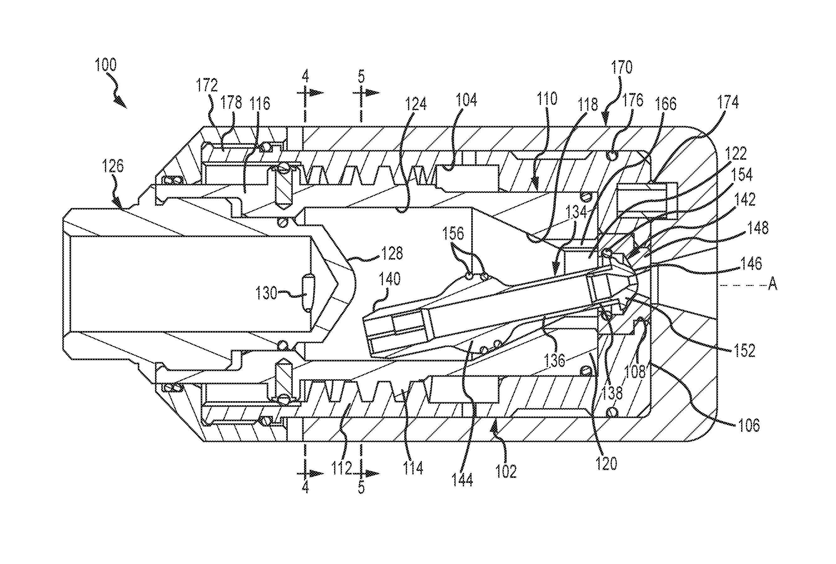
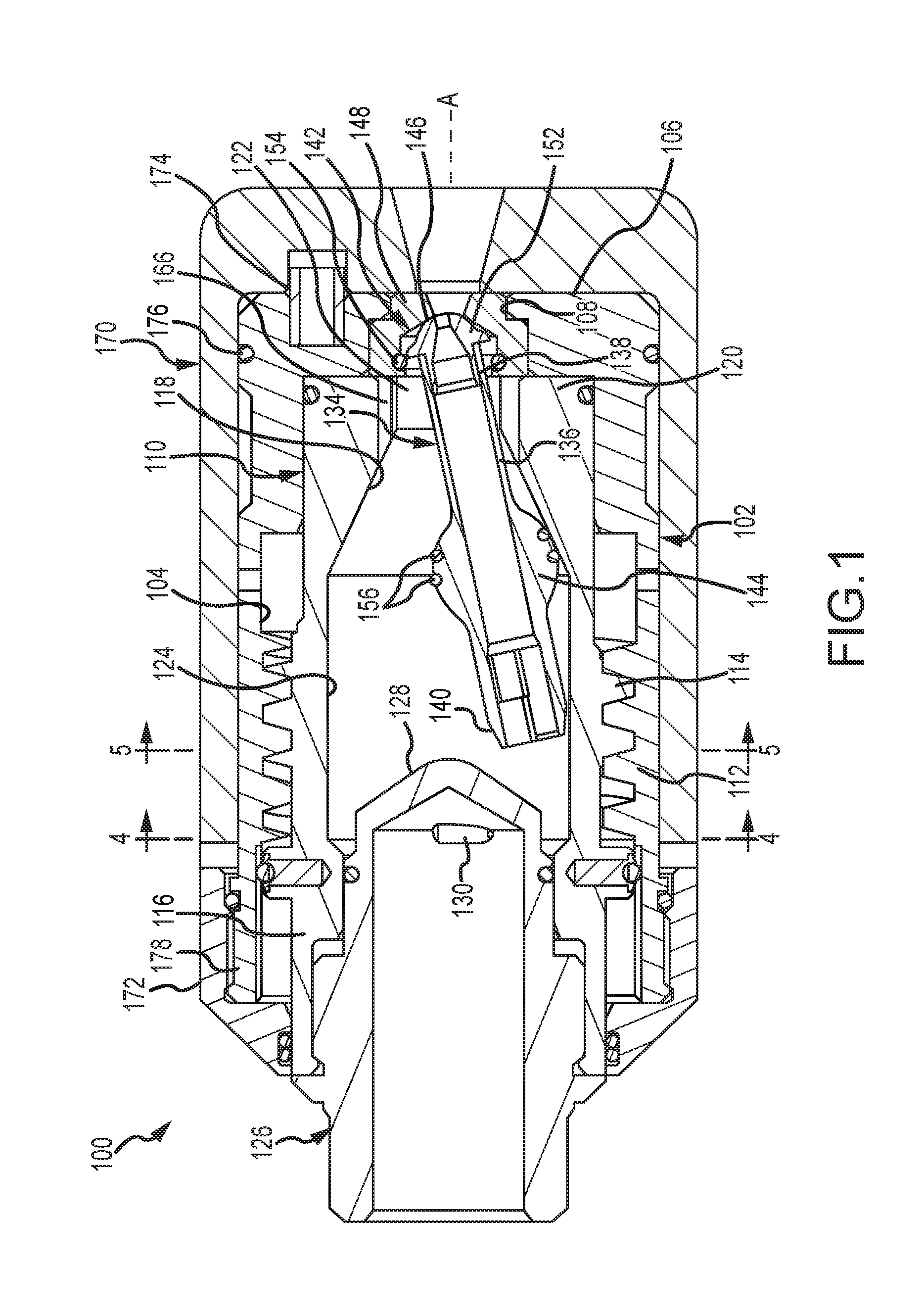
[0019]A longitudinal sectional view of a nozzle apparatus 100 in accordance with the present disclosure is shown in FIG. 1. The apparatus 100 is generally symmetrical about a central axis A through the apparatus 100. The apparatus 100 includes a cup shaped outer housing 102 having a cylindrical wall portion 104 and a generally flat radially extending bottom portion 106 extending outward to the wall portion 104 from a central opening 108.

[0020]A tubular inner housing 110 is carried within the outer housing 102 via complementary features, preferably internal ACME threads 112 on the wall portion 104 of the outer housing 102 and external ACME threads 114 on the exterior of the inner housing 110. The inner housing 110 has a proximal end portion 116, a conical inner wall portion 118 and a distal end portion 120 that has a central passage 122 therethrough. The inner housing 110 further has an inner cylindrical wall portion 124 between the proximal end portion 116 and the conical inner wall...


PUM


Abstract

A rotary nozzle apparatus is disclosed which includes a cup shaped outer housing having a central axis, a wall portion and a bottom portion. A tubular inner housing is centered on the central axis within the outer housing engaging the wall portion of the outer housing. A distal end of an elongated tubular nozzle body carries a nozzle head extending through a passage out of the inner housing to an opening through the bottom portion of the outer housing. The nozzle body is configured to rotate around a conical inner wall portion of the inner housing in response to rotational fluid flow into the inner housing. The angle of the nozzle body with respect to the central axis, and hence fluid spray angle may be adjusted from a wide spray angle to an axial stream by changing spacing between the bottom portion of the outer housing and the inner housing.

Description

CROSS REFERENCE TO RELATED APPLICATIONS[0001]This application claims the benefit of priority of U.S. Provisional Patent Application No. 62 / 119,462 filed Feb. 23, 2015, entitled Internally Adjustable Spray Angle Rotary Nozzle, the content of which is incorporated by reference herein in its entirety.BACKGROUND OF THE DISCLOSURE[0002]The present disclosure is directed to high pressure fluid rotary nozzle systems. In particular, embodiments of the present disclosure are directed to an internally adjustable spray angle rotary nozzle.[0003]Rotary nozzles provide a means of directing a concentrated high pressure stream of fluid over a relatively large surface area by directing the stream in a continuously changing direction about a central axis through the nozzle assembly. One such nozzle is described in U.S. Pat. No. 8,820,659 B2. A rotary nozzle body within a housing rotates around the interior of the housing causing the stream of fluid exiting the nozzle to cover a large area. However, ...

Claims


Application Information

Patent Timeline
IPC IPC(8): B05B3/04B05B1/30
CPCB05B1/30B05B3/0463B05B3/021B05B13/0278
Inventor ANDERSEN, COLTONWRIGHT, DOUGLAS E.
Owner STONEAGE
Why Eureka
Try Eureka