
Method of and apparatus for adaptive control of data buffering in a data transmitter

a data transmitter and data buffer technology, applied in the field of methods and apparatus for transmitting data, can solve the problems of unsatisfactory, bursty data delivery, and inability to adapt to the flow of data,

Inactive Publication Date: 2006-07-27
QUALCOMM INC
View PDF2 Cites 22 Cited by
  • Summary
  • Abstract
  • Description
  • Claims
  • Application Information

AI Technical Summary

Benefits of technology

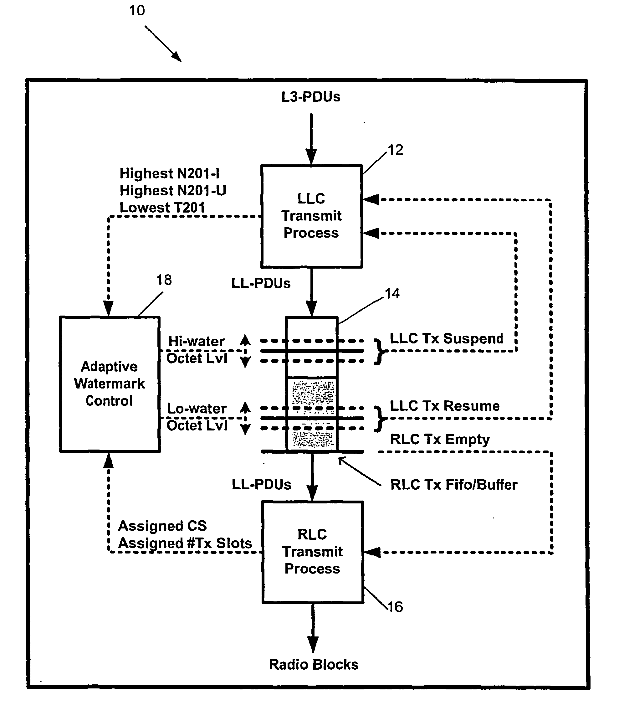
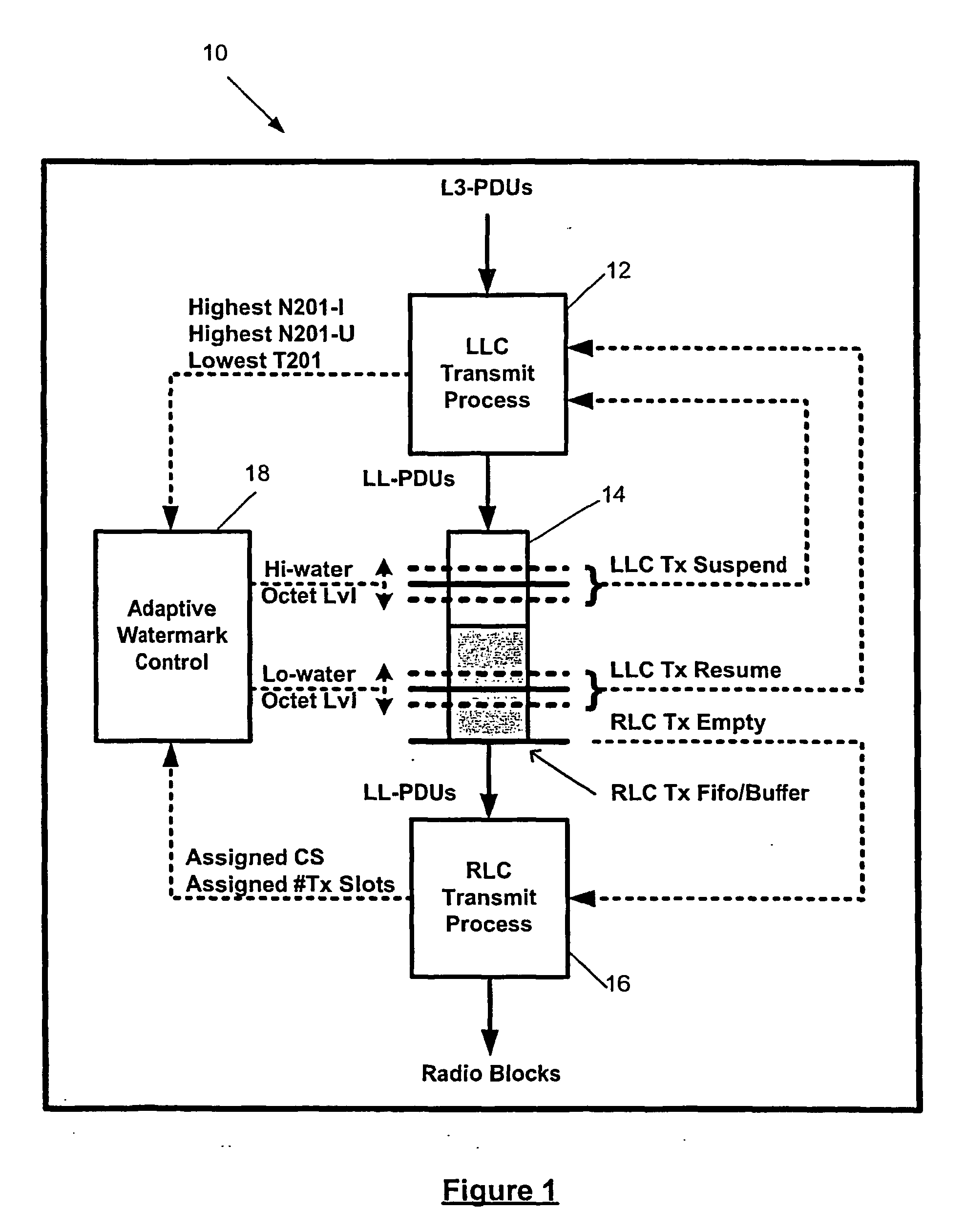
[0015] According to a further aspect of the invention there is provided a data transmitter in which incoming data for transmission is divided into data blocks and passed in frame transmission order to a radio link stage via a serial frame buffer which holds the data until the radio link is able to transmit it, the incoming data having associated with it various parameters and the radio link stage having allocated to it radio link resources which parameters and resources change independently of each other from time to time and are supplied to a controller which calculates high and low buffer levels therefrom and controls the passing of the data frames through the frame buffer to maintain the number of frames in the buffer at any instant of time at a level between the calculated high and low levels.

Problems solved by technology

One problem with data transfer is that it can arrive in bursts depending on the source and / or medium from which it arrives.
Plainly, such “bursty” delivery of data is undesirable because it places overheads in terms of data management on the receiving entity.
While this approach will undoubtedly work, it is less than satisfactory because the buffer will have to be sufficiently large to hold data in the situation where a large burst of data arrives followed by a period of time when no data arrives.
Most of the time a buffer of that size will be less than full and will therefore be underutilized.
This is, of course, a waste of resources and is therefore undesirable.

Method used


Image

  • Method of and apparatus for adaptive control of data buffering in a data transmitter
  • Method of and apparatus for adaptive control of data buffering in a data transmitter
  • Method of and apparatus for adaptive control of data buffering in a data transmitter

Examples


Embodiment Construction

[0020] Turning now to FIG. 1 of the accompanying drawings, there is shown a general packet radio system (GPRS) transmit entity 10 (e.g. a mobile station MS) in which protocol data units (PDUs) are delivered from a source (not shown) to a logical link control (LLC) layer 12 to be prepared for transmission. The SNDCP is logically situated below the network layer and above the LLC layer. Typically the data will be delivered to the LLC layer 12 from a layer known as the Sub-Network Dependant Convergence Protocol (SNDCP) which provides support for a variety of network layer protocols and performs multiplexing of data coming from different sources before the data is sent to the logical link control (LLC) layer 12.

[0021] The data from the SNDCP layer (not shown) is segmented by the LLC layer 12 into maximum length LLC frames, known as logical link protocol data units (LL-PDUs) The LL-PDUs are then input to a radio link control (RLC) FIFO buffer 14 where they are held until required by an ...


PUM


Abstract

A data transmitter (10) divides incoming data for transmission into data blocks and passes them in frame transmission order to a radio link stage (16) via a serial frame buffer (14). The buffer (14) holds the data frames until the radio link stage (16) is able to transmit them. The incoming data has associated with it various parameters. The radio link stage (16) has allocated to it radio link resources. The parameters and resources, which change independently of each other from time to time, are supplied to a controller (18) which calculates high and low buffer levels therefrom. The controller (18) controls the passing of the data frames through the frame buffer (14) to maintain the number of frames in the buffer at any instant of time at a level between the calculated high and low levels.

Description

BACKGROUND OF THE INVENTION [0001] I. Field of the Invention [0002] The present invention relates generally to a method of and apparatus for transmitting data. The invention also relates to a method of and apparatus for adaptive control of data buffering in a transmitter. The method and apparatus are well suited for use in the GPRS standard but are not limited to such an application. [0003] II. Description of the Related Art [0004] The general packet radio system (GPRS) is a packet data based communication system that has been developed for GSM networks with the aim of providing networks built to this standard with a way to handle higher data speeds and packet switched connections. GPRS can also be used in time division multiple access (TDMA) networks (IS-136). It is intended to provide a transitional path to third generation (3G) wireless data services It enables the introduction of packet switching and Internet Protocol (IP). The GPRS standard is now well defined and is currently ...

Claims


Application Information

Patent Timeline
IPC IPC(8): G06F15/16H04L47/30
CPCH04L47/10H04L47/14H04L47/263H04L47/30H04W28/14H04W28/18H04L47/127H04L2001/125H04W28/02H04Q11/04H04W8/04
Inventor ROBINSON, NIGEL P.
Owner QUALCOMM INC
Learn More