
Transmission power control method and base station device

a transmission power and base station technology, applied in power management, high-level techniques, wireless communication, etc., can solve the problems of reducing the subscriber capacity (system capacity) of the entire system, deteriorating communication quality of speech communication, and reducing the transmit power available for other channels such as dpch., so as to prevent excessive transmit power

Inactive Publication Date: 2006-07-27
PANASONIC CORP
View PDF20 Cites 42 Cited by
  • Summary
  • Abstract
  • Description
  • Claims
  • Application Information

AI Technical Summary

Benefits of technology

[0008] It is an object of the present invention to provide a method for controlling transmit power and a base station apparatus capable of appropriately controlling transmit power of a common channel for an MBMS so as to prevent the transmit power from becoming excessive.
[0009] The present inventor et al. have come up with the present invention by noticing the fact that while an S-CCPCH has only a downlink direction, a DPCH has both directions of uplink and downlink and discovering that it is possible to use an uplink DPCH to transmit a TPC command for the S-CCPCH to a base station. Thus, in order to solve the above described problem and attain the object, the present invention allows each mobile station in an MBMS to transmit both a TPC command for a downlink common channel and a TPC command for a downlink dedicated channel to a base station through an uplink dedicated channel. In this way, it is possible to appropriately control transmit power of a common channel used to transmit MBMS data.

Problems solved by technology

For this reason, for a mobile station located near the base station, its reception quality becomes excessive, which results in waste.
Furthermore, interference with other cells also increases causing a reduction of the subscriber capacity (system capacity) of the entire system.
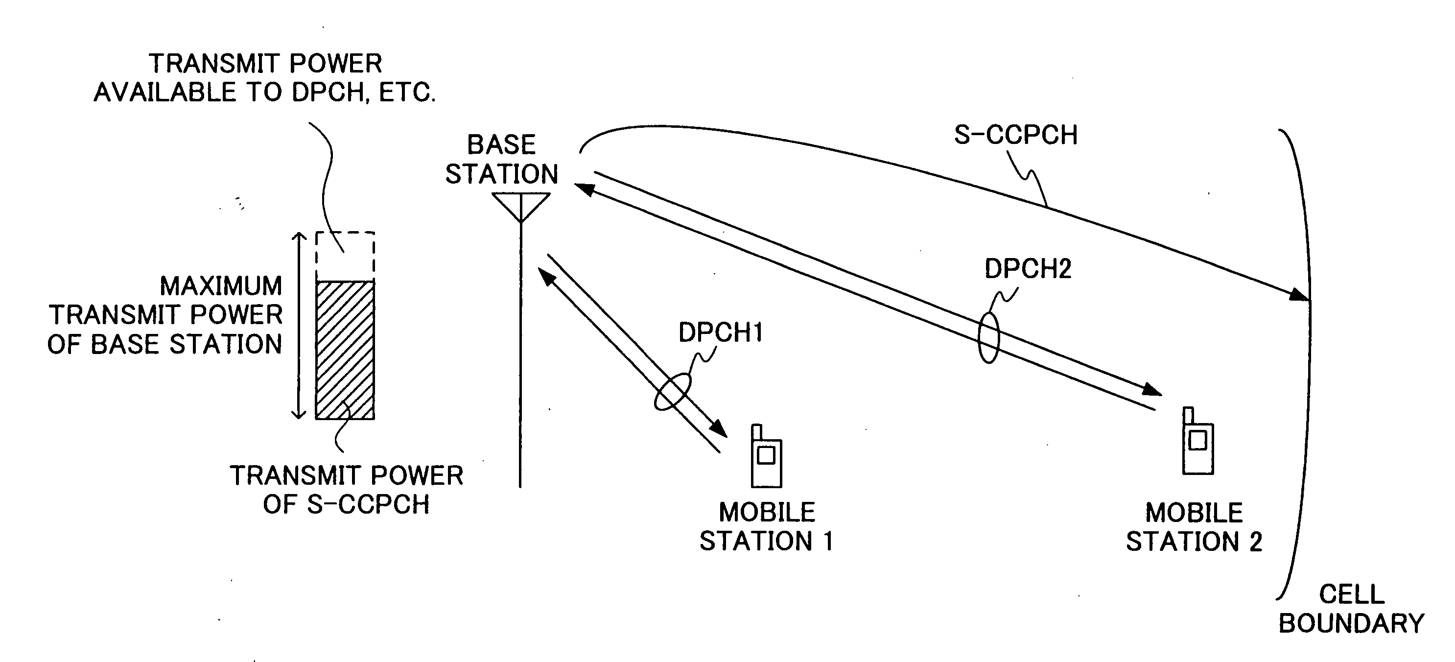
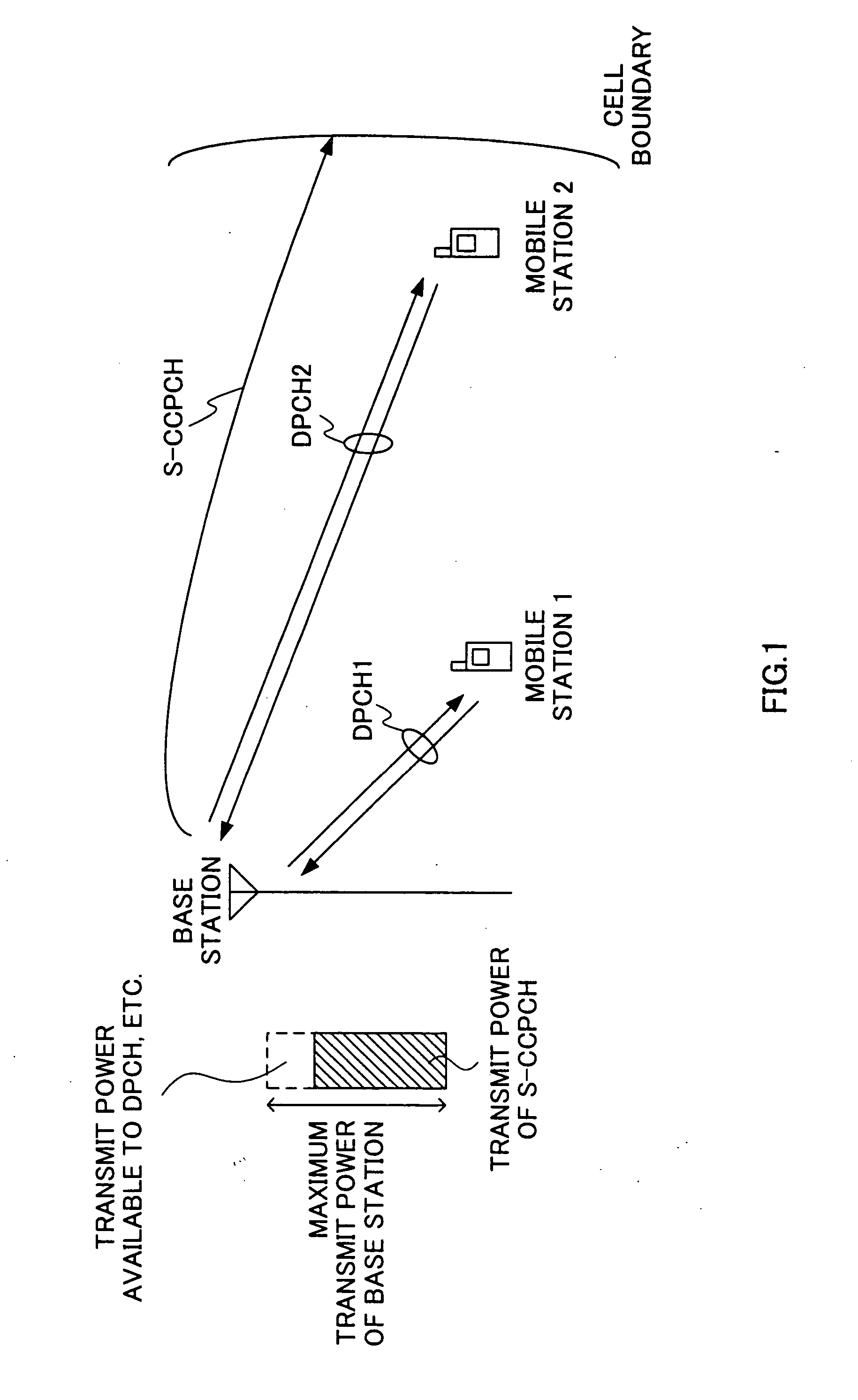
Furthermore, an upper limit (maximum transmit power at the base station) of total transmit power of all channels is predetermined for the base station, and therefore if the transmit power of the S-CCPCH is large as shown in FIG. 1, transmit power available for other channels such as the DPCH is relatively reduced and communication quality of a speech communication, etc., deteriorates.

Method used


Image

  • Transmission power control method and base station device
  • Transmission power control method and base station device
  • Transmission power control method and base station device

Examples


embodiment 1

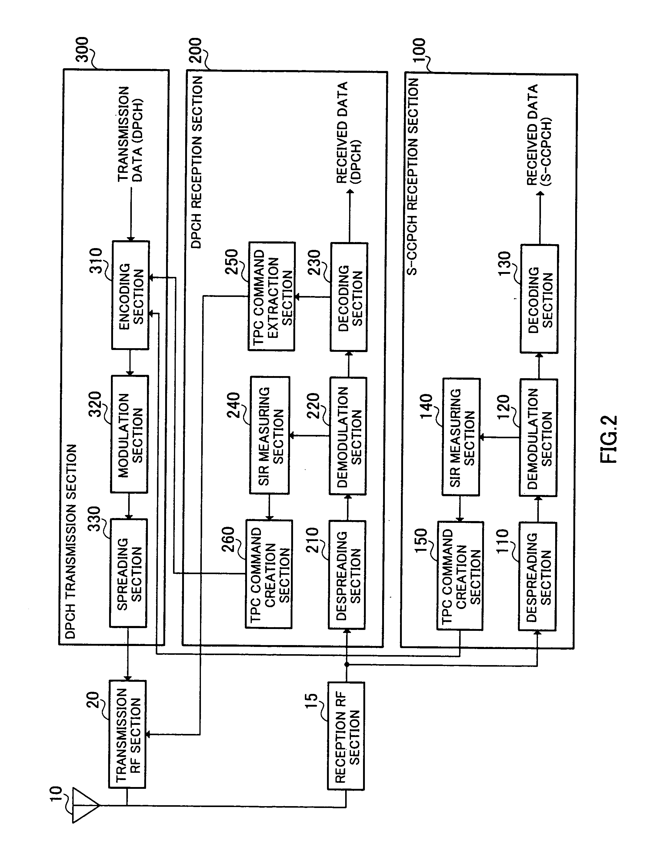
[0028]FIG. 2 is a block diagram showing a configuration of a mobile station according to Embodiment 1 of the present invention. This mobile station is used in a mobile communication system in which an MBMS is carried out.

[0029] The mobile station shown in FIG. 2 includes an antenna 10, areception RF section 15, an S-CCPCH reception section 100, a DPCH reception section 200, a DPCH transmission section 300 and a transmission RF section 20. The S-CCPCH reception section 100 includes a despreading section 110, a demodulation section 120, a decoding section 130, an SIR measuring section 140 and a TPC command creation section 150. The DPCH reception section 200 includes a despreading section 210, a demodulation section 220, a decoding section 230, an SIR measuring section 240, a TPC command extraction section 250 and a TPC command creation section 260. The DPCH transmission section 300 includes an encoding section 310, a modulation section 320 and a spreading section 330.

[0030] The rec...

embodiment 2

[0053] This embodiment controls transmit power of a downlink S-CCPCH to power equal to transmit power of a downlink DPCH under transmit power control according to a TPC command or power with an addition of an offset.

[0054]FIG. 8 is a block diagram showing a configuration of a mobile station according to Embodiment 2 of the present invention. The same components as those of Embodiment 1 (FIG. 2) are assigned the same reference numerals and explanations thereof will be omitted. The mobile station shown in FIG. 8 adopts a configuration with the SIR measuring section 140 and TPC command creation section 150 omitted from the S-CCPCH reception section 100 of the mobile station shown in FIG. 2. That is, in the mobile station shown in FIG. 8, no TPC command for the downlink S-CCPCH is created and only TPC commands for the downlink DPCH are input from a TPC command creation section 260 of a DPCH reception section 200 to an encoding section 310. Therefore, TPC commands for the downlink DPCH ...

embodiment 3

[0064] This embodiment controls the amount of the offset according to Embodiment 2.

[0065]FIG. 11 is a block diagram showing a configuration of a mobile station according to Embodiment 3 of the present invention. The same components as those in Embodiment 2 (FIG. 8) are assigned the same reference numerals and explanations thereof will be omitted. The mobile station shown in FIG. 11 adopts a configuration with a response signal creation section 160 added to the S-CCPCH reception section 100 of the mobile station shown in FIG. 8.

[0066] A decoding section 130 of the S-CCPCH reception section 100 inputs a CRC result of the S-CCPCH, that is, CRC=OK (no error) or CRC=NG (error found) to the response signal creation section 160. When CRC=OK is input, the response signal creation section 160 creates an ACK (Acknowledgement: positive response) signal and inputs the ACK signal to an encoding section 310. On the other hand, when CRC=NG is input, the response signal creation section 160 creat...


PUM


Abstract

In order to appropriately control transmit power of a common channel for an MBMS (Multimedia Broadcast / Multicast Service) so as not to become excessive, a mobile station 1 transmits a TPC command for an S-CCPCH to a base station through an uplink DPCH1 and a mobile station 2 transmits a TPC command for an S-CCPCH to the base station through an uplink DPCH2. When either one of the TPC command for the S-CCPCH transmitted from the mobile station 1 and the TPC command for the S-CCPCH transmitted from the mobile station 2 is a TPC command instructing “Up”, the base station increases transmit power of the downlink S-CCPCH and decreases transmit power of the downlink S-CCPCH when both TPC commands instruct “Down”.

Description

TECHNICAL FIELD [0001] The present invention relates to a method for controlling transmit power and base station apparatus. BACKGROUND ART [0002] In the field of mobile communications, technological studies on a multimedia broadcast / multicast service (hereinafter referred to as “MBMS”) are being carried forward recently (e.g., see “3GPP TS 22.146 V6.0.0 (2002-06): 3rd Generation Partnership Project; Technical Specification Group Services and System Aspects; Multimedia Broadcast / Multicast Service; Stage 1 (Release 6) June 2002”). A communication carried out in an MBMS is not a one-to-one (Point to Point: P-to-P) communication but one-to-multi (Point to Muiti: P-to-M) communication. That is, in the MBMS, one base station transmits the same data (e.g., music data and video image data, etc.) to a plurality of mobile stations simultaneously. [0003] The MBMS has a broadcast mode and multicast mode. While the broadcast mode is a mode in which information is transmitted to all mobile statio...

Claims


Application Information

Patent Timeline
IPC IPC(8): H04B7/00H04Q7/20H04B7/005H04W52/08H04B7/26H04W52/32
CPCH04W52/08H04W52/322H04W52/325H04W52/327Y02B60/50H04W52/54Y02D30/70
Inventor NISHIO, AKIHIKOKASAPIDIS, MAKISHIRAMATSU, KATSUHIKOYOSHII, ISAMUUEHARA, TOSHIYUKINAKA, KATSUYOSHI
Owner PANASONIC CORP
Learn More