
System for establishing a sample cover on a substrate

a substrate and sample technology, applied in the field of clamping devices, can solve the problems of varying internal chamber volumes, broken slides, inadequate sealing of chambers, etc., and achieve the effects of reducing costs, and reducing the number of components

Inactive Publication Date: 2006-07-27
DAKOAS
View PDF21 Cites 37 Cited by
  • Summary
  • Abstract
  • Description
  • Claims
  • Application Information

AI Technical Summary

Benefits of technology

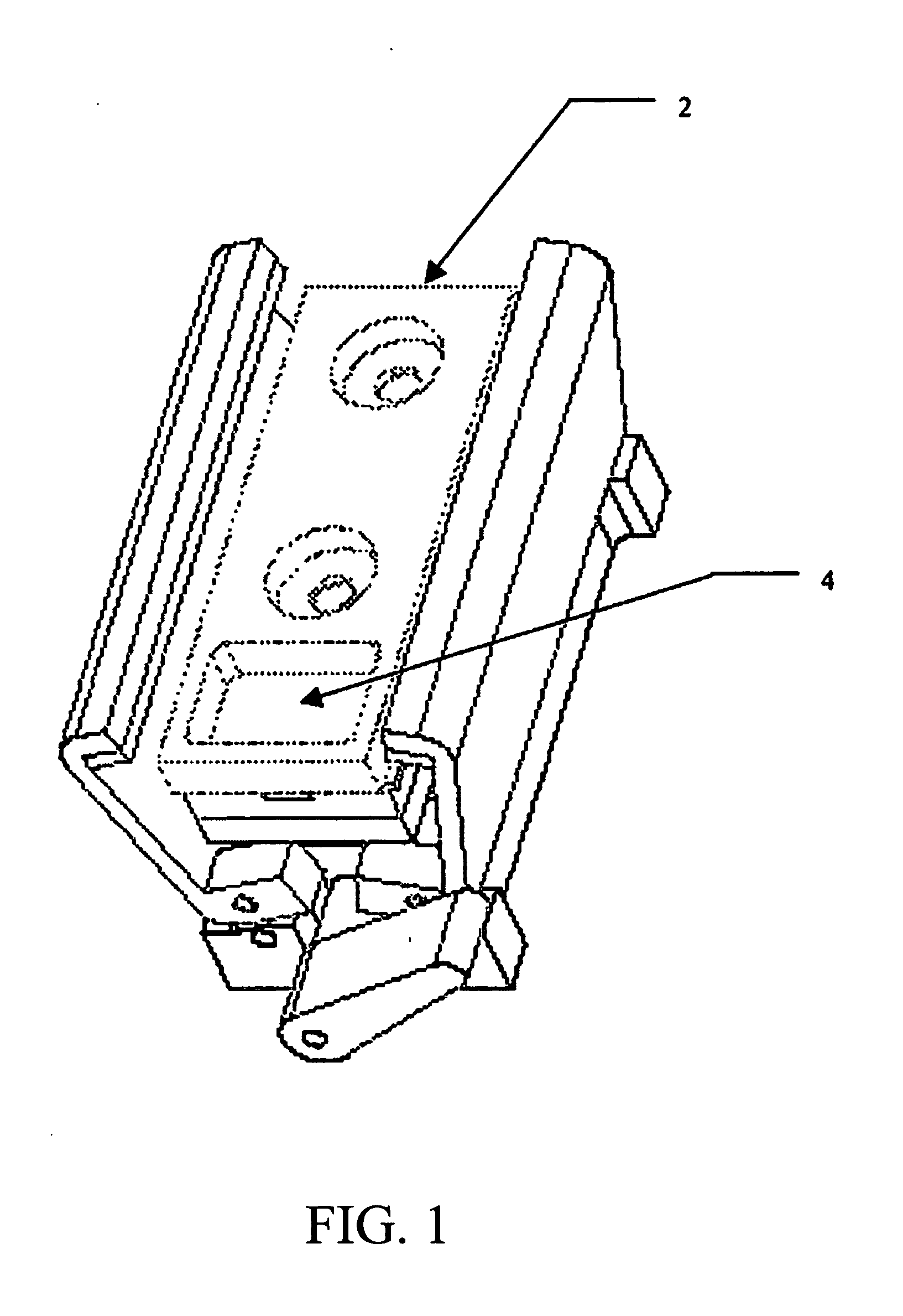
[0028] The disc springs may not directly contact the support substrate or the support cover. Instead, the springs may “push” against a heater base / stem and base. Both the heater base / stem and the base may be sufficiently rigid to prevent significant bending under the forces developed by the clamping device. Minimizing the bending of the heater base / stem may provide more uniform clamping pressure to the substrate and cover. The more uniformity of the clamping pressure the less likely support substrates will break when clamped.
[0042] Another embodiment of the invention may use a single clamping device to secure and seal a single support cover with two or more individual integral seals to two or more support substrates. Each support substrate could have its own dedicated chamber formed by the individual seal and the support cover. The novelty may be a significant reduction in the number of components resulting in lower costs and smaller instruments. Similar clamp components could be used, but they may differ in size to accommodate the larger cover and higher number of support substrates. Rigidity may become more of a concern when clamping multiple substrates to a single cover with a single clamp device. The further away the slides are from the clamping center axis (axis along spring stack), the larger the cantilever and the more likely bending will occur affecting overall clamp force. One way to increase the overall rigidity is to increase the thickness of key components such as the heater base / stem. Automated clamp actuation and substrate and cover insertion may become increasingly practical for totally automated instruments for IHC, ISH / FISH or special stains using small volumes of reagents (i.e. 10-200 μL). Total automation can free the user to perform other tasks while the instrument is operating.

Problems solved by technology

Non-repeatable force values may lead to varying internal chamber volumes, broken slides or inadequately sealed chambers.

Method used


Image

  • System for establishing a sample cover on a substrate
  • System for establishing a sample cover on a substrate
  • System for establishing a sample cover on a substrate

Examples


example 1

COL

[0094] A biological specimen (tissue sample) is fixed in formalin and then embedded with paraffin by standard procedures. The embedded tissue is attached to a glass microscope slide. The tissue is then deparaffinized while on the slide by standard deparaffinizing procedures. The glass slide with the attached biological specimen is placed on top of the heater plate. A disposable support cover with an inlet and outlet port and integral seal is placed on top of the glass slide. The latches of the clamp mechanism are closed over the cover and the clamp is engaged by rotating the lever counterclockwise. The cover now makes a sealed chamber (except for the open ports) over the biological specimen on the slide. Reagents and wash buffers are then injected into the chamber through the inlet port in the following order. Each reagent and wash buffer application has its own temperature requirements and incubation times.

STEP NO.REAGENTTEMP. ° C.TIME1Proteolytic treatment, 10-200 μL37° C.30m...

example 2

OCOL

[0098] A biological specimen (tissue sample) is fixed in formalin and then embedded with paraffin by standard procedures. The embedded tissue is attached to a glass microscope slide. The tissue is then deparaffinized while on the slide by standard deparaffinizing procedures. The glass slide with the attached biological specimen is placed on top of the heater plate. A disposable support cover with an inlet and outlet port and integral seal is placed on top of the glass slide. The latches of the clamp mechanism are closed over the cover and the clamp is engaged by rotating the lever counterclockwise. The cover now makes a sealed chamber (except for the open ports) over the biological specimen on the slide. Reagents and wash buffers are then injected into the chamber through the inlet port in the following order. Each reagent and wash buffer application has its own temperature requirements and incubation times.

STEPNO.REAGENTTEMP. ° C.TIME 1Dehydrate, 100% ethanol 1-5 mlRT10minute...

example 3

ARRAY PROTOCOL

[0100] A glass slide with the attached DNA microarray is placed on top of the heater plate. A disposable support cover with an inlet and outlet port and integral seal is placed on top of the glass slide. The latches of the clamp mechanism are closed over the cover and the clamp is engaged by rotating the lever counterclockwise. The cover now makes a sealed chamber (except for the open ports) over the microarray on the slide. Reagents and wash buffers are then injected into the chamber through the inlet port in the following order. Each reagent and wash buffer application has its own temperature requirements and incubation times.

STEP NO.REAGENTTEMP. ° C.TIME 1Prehybridization solution,37° C.0.5-2hrs10-200 μL. Sealinlet / outlet ports2Remove port seals3Wash w / dH20 1-5 mlRT4Fluorescent target65° C.2minuteshybridization solution,10-200 μL.Seal inlet / outlet ports5Target hybridization solution37° C.16hrs.6Remove port seals7Wash .1X SSC w / .1% SDS,RT1-5 ml8Wash .1X SSC, 1-5 ml...


PUM

PropertyMeasurementUnit
volumesaaaaaaaaaa
temperatureaaaaaaaaaa

Abstract

The invention provides a manually operated or automated clamping means to seal a solid support substrate to a solid support cover creating a uniform environmental chamber above a specimen mounted to the support substrate. The clamping means may consist of several components that may act ad a system to provide a repeatable and uniform clamping load to the substrate and cover.

Description

I. BACKGROUND [0001] This invention relates to a novel clamping device for providing repetitive and uniform compression of a solid support cover to a solid support substrate with a biological sample mounted on it (i.e. a glass microscope slide). The clamping device may also create a seal by compressing a sealing material (i.e. a gasket, o-ring or similar material) between the cover and the solid support substrate. The invention may also eliminate the inherent variability in clamping force developed by users with different physical abilities. [0002] One embodiment of the present invention describes a clamping device that may be used to secure a solid support cover to a solid support substrate with a biological specimen on the surface apposed to the cover. The clamp is innovative in that it provides uniform clamping force along the edges of the cover, minimizes the potential for broken support substrates, and is not dependent on the user's physical abilities. [0003] Biological specime...

Claims


Application Information

Patent Timeline
Patent Type & Authority Applications(United States)
IPC IPC(8): G01N1/00B01L3/00B01L7/00B01L9/00G01N1/31
CPCB01L3/508B01L7/00B01L9/52B01L2200/0689Y10T436/25B01L2300/0822B01L2300/1805G01N1/31G01N1/312B01L2300/0636
Inventor TESTA, GREGORY A.HUG, HANS A.
Owner DAKOAS
Learn More