
Anchor

a self-drilling, anchoring technology, applied in the direction of fastening means, dowels, mechanical equipment, etc., can solve the problems of difficult installation, high price of toggle bolts, unreliable, etc., and achieve the effect of high pullout strength and easy installation

Inactive Publication Date: 2006-07-27
ILLINOIS TOOL WORKS INC
View PDF21 Cites 40 Cited by
  • Summary
  • Abstract
  • Description
  • Claims
  • Application Information

AI Technical Summary

Benefits of technology

[0088] Advantages of the invention include greater pull out than current products, and greater shear strength in comparison to size. The invention is cost competitive due to this size / strength advantage and its one-piece construction. Other advantages include the self-drilling feature, low installation torque for mounting a screw, no blistering under the drywall paper around the head, more stability during drilling, excellent fit with all types of screwdriver Phillips size, head seats flush with the drywall, does not break during installation in drywall, and a robust Phillips recess that does not crack around the outer diameter.

Problems solved by technology

Because drywall is a friable material, mounting articles thereto can be difficult.
Toggle bolts have been known to be expensive, unreliable, and difficult to install because they typically are not self-drilling.

Method used


Image

  • Anchor
  • Anchor
  • Anchor

Examples


Embodiment Construction

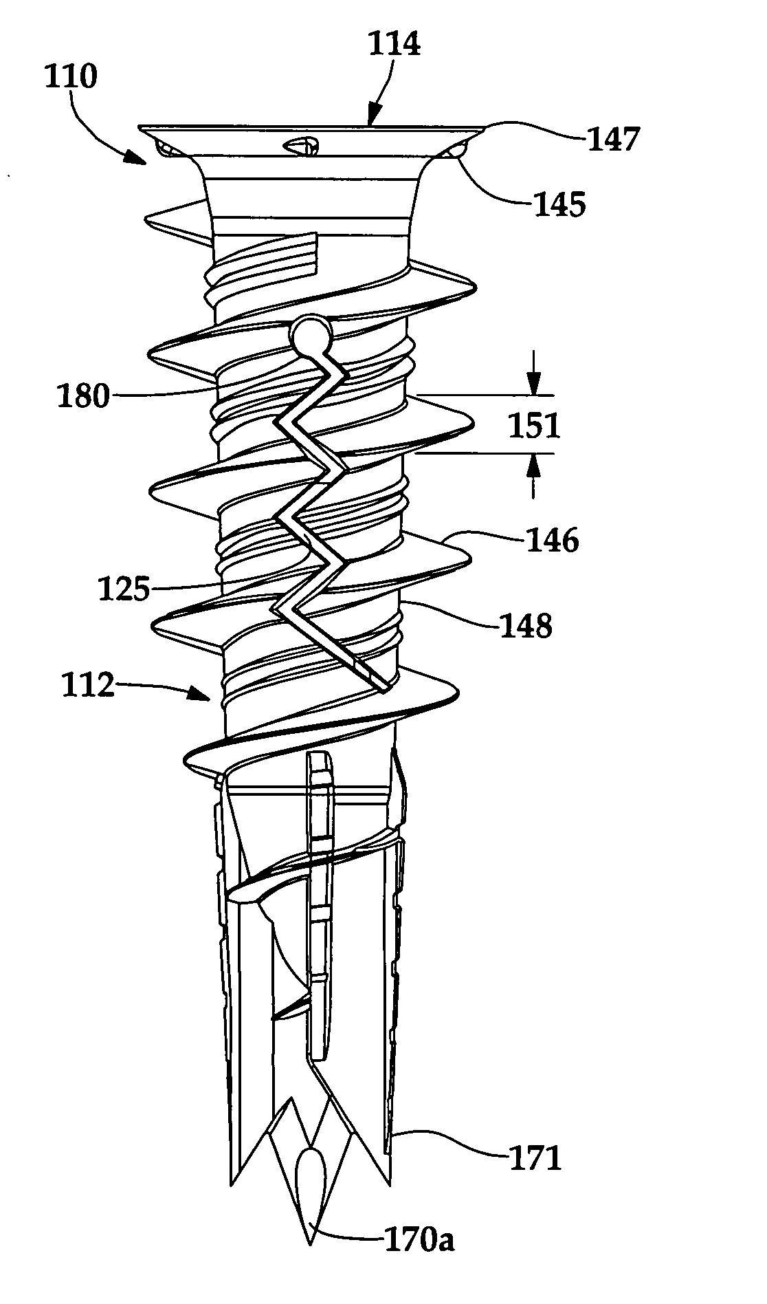
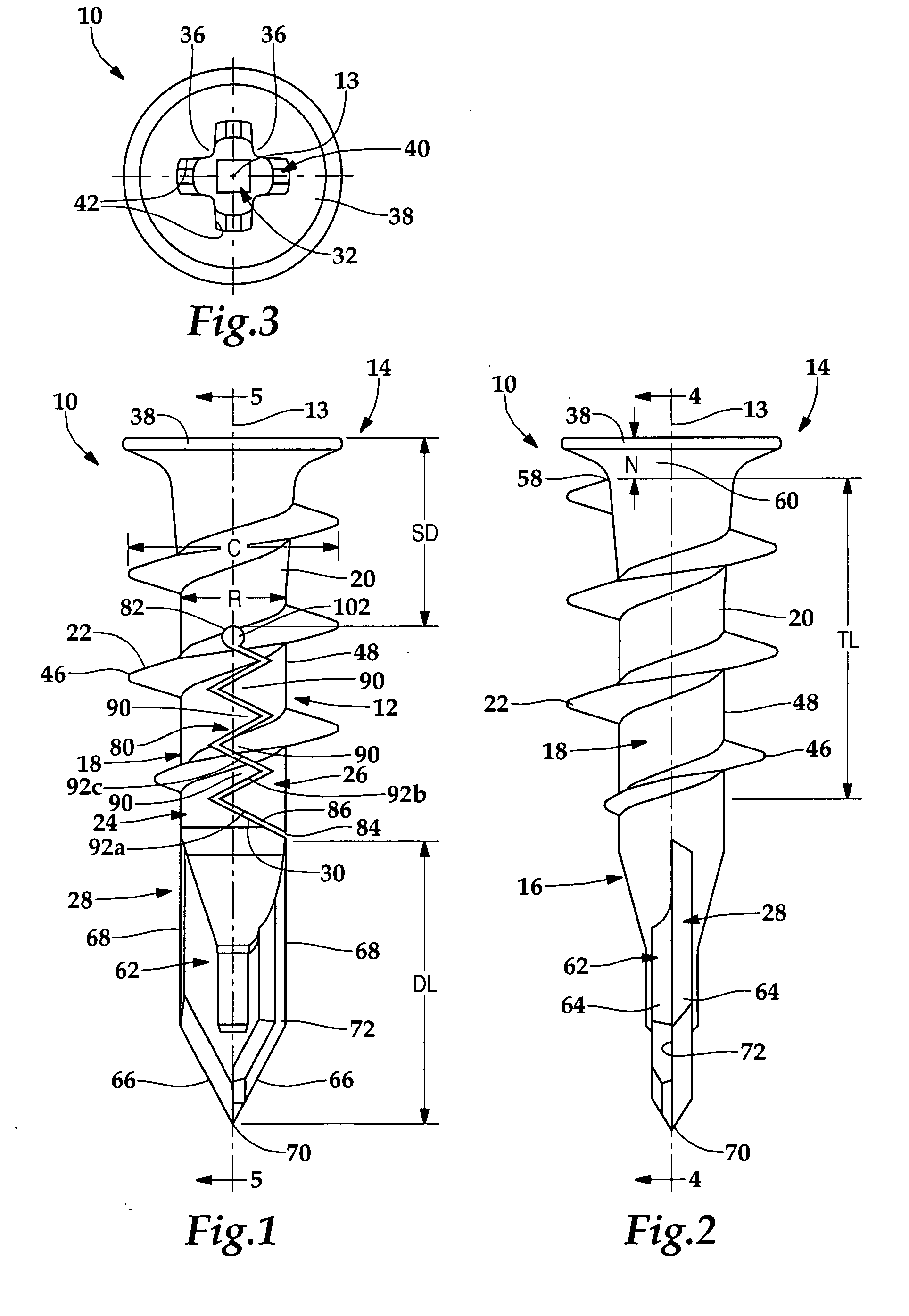
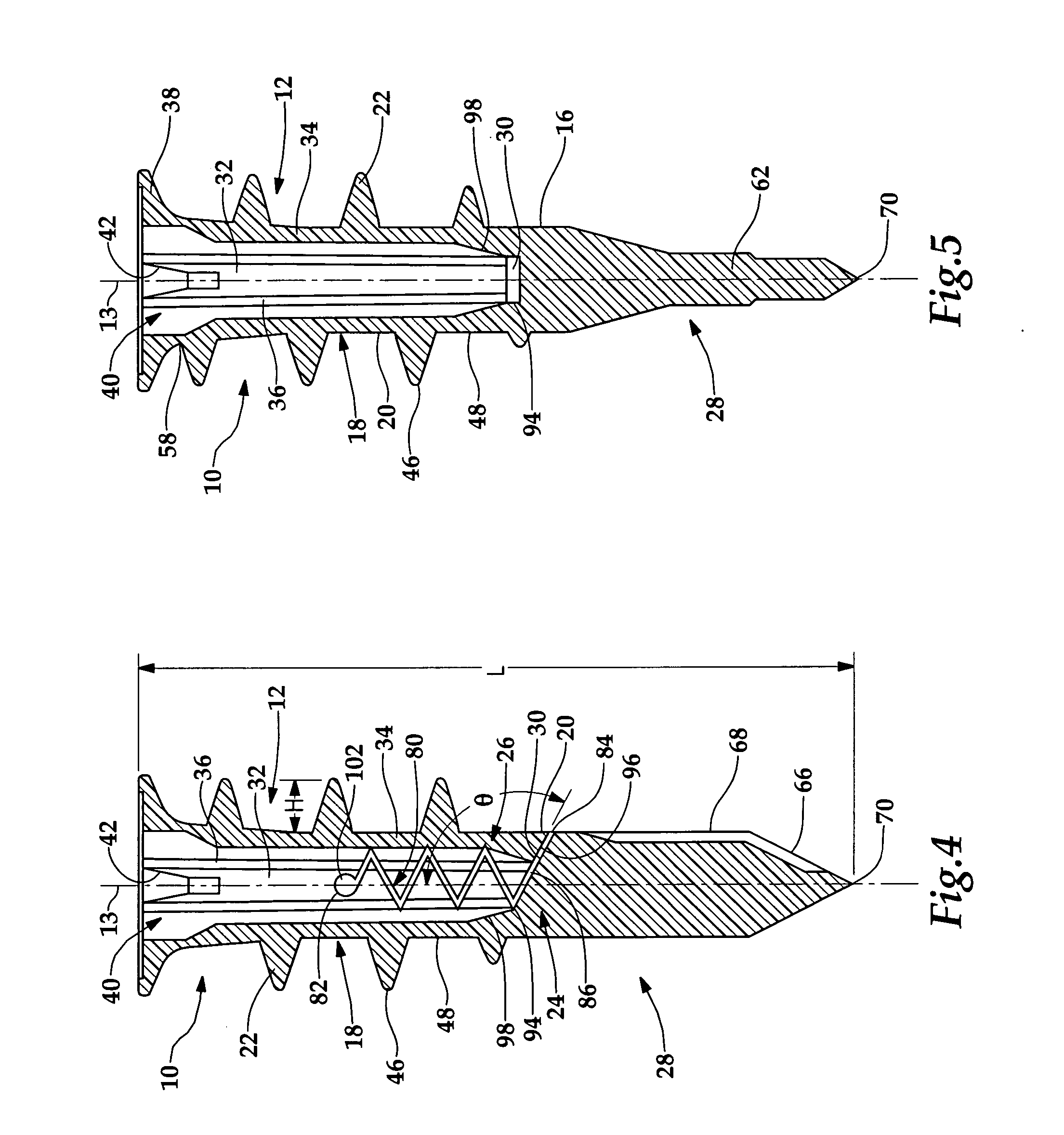
[0035] Referring to FIGS. 1-7, a self-drilling anchor 10 is shown for use in a friable material, such as drywall 1. Anchor 10 includes a body 12 having an axis 13, a flanged rear end 14, a drilling front end 16 and a generally cylindrical central portion 18 therebetween having an outer surface 20 with a thread 22 disposed thereon, wherein body 12 forks, beginning at a predetermined distance SD from flanged rear end 14, into a first leg 24 and a second leg 26, first leg 24 extending forwardly into a drilling tip 28 and having a generally rearward facing shoulder 30 angled obtusely outwardly with respect to axis 13, wherein body 12 has an axial bore 32 for receiving an elongate mounting fastener 2, axial bore 32 extending substantially through flanged end 14 and central portion 18 and leading to shoulder 30, wherein anchor 10 has a drilling mode wherein second leg 26 nests behind shoulder 30 of first leg 24, FIG. 1, and an anchoring mode wherein legs 24, 26 are pivoted apart from one ...


PUM


Abstract

A self-drilling anchor for use in a friable material comprises a body having an axis, a flanged rear end, a drilling front end and a generally cylindrical portion therebetween having an outer surface with a thread disposed thereon, wherein the body forks, beginning at a predetermined distance from the flanged rear end, into a first leg and a second leg, the first leg extending forwardly into a drilling tip and having a generally rearward facing shoulder angled obtusely outwardly with respect to the axis, wherein the body has an axial bore for receiving an elongate fastener, the axial bore extending substantially through the flanged end and the generally cylindrical portion and leading to the generally rearward facing shoulder, wherein the anchor has a drilling mode wherein the second leg nests behind the generally rearward facing shoulder of the first leg, and an anchoring mode wherein the legs are pivoted apart from one another.

Description

[0001] This application is a continuation-in-part of U.S. patent application Ser. No. 10 / 772,677 filed on Feb. 5, 2004.BACKGROUND OF THE INVENTION [0002] 1. Field of the Invention [0003] The present invention is directed to an anchor for use in a friable material, particularly to a self-drilling anchor for use in drywall. [0004] 2. Description of the Related Art [0005] Because drywall is a friable material, mounting articles thereto can be difficult. In the past, self-drilling anchors have been used. However, self-drilling anchors have been known to achieve pullout strength of only about 50 to 70 pounds. [0006] 1 For heavier loads, toggle bolts have been used. Toggle bolts have been known to be expensive, unreliable, and difficult to install because they typically are not self-drilling. [0007] What is needed is an anchor for a friable material that is easy to install and provides high pullout strength for heavy loads. BRIEF SUMMARY OF THE INVENTION [0008] A self-drilling anchor is p...

Claims


Application Information

Patent Timeline
IPC IPC(8): F16B13/04F16B13/00F16B13/12
CPCF16B13/002
Inventor PANASIK, CHERYL L.ERNST, RICHARD J.MANSOUR, NAIMGRIMM, JOHN P.MUELLER, DAVID W.MONJE, AARON V.
Owner ILLINOIS TOOL WORKS INC
Learn More