
Integrating sensors over a digital link

a technology of digital link and sensor, applied in welding monitoring devices, manufacturing tools, electric heating, etc., can solve the problems of difficult configuration of disparate welding units with particular sensors, frequent change of applications associated with welding units, etc., and achieve the effect of reducing deficiencies in conventional systems and enabling remote modification of process monitoring applications

Active Publication Date: 2006-07-27
LINCOLN GLOBAL INC
View PDF15 Cites 130 Cited by
  • Summary
  • Abstract
  • Description
  • Claims
  • Application Information

AI Technical Summary

Benefits of technology

[0006] The following presents a simplified summary of the invention in order to provide a basic understanding of some aspects of the invention. This summary is not an extensive overview of the invention. It is intended to neither identify key or critical elements of the invention nor delineate the scope of the invention. Its sole purpose is to present some concepts of the invention in a simplified form as a prelude to the more detailed description that is presented later.
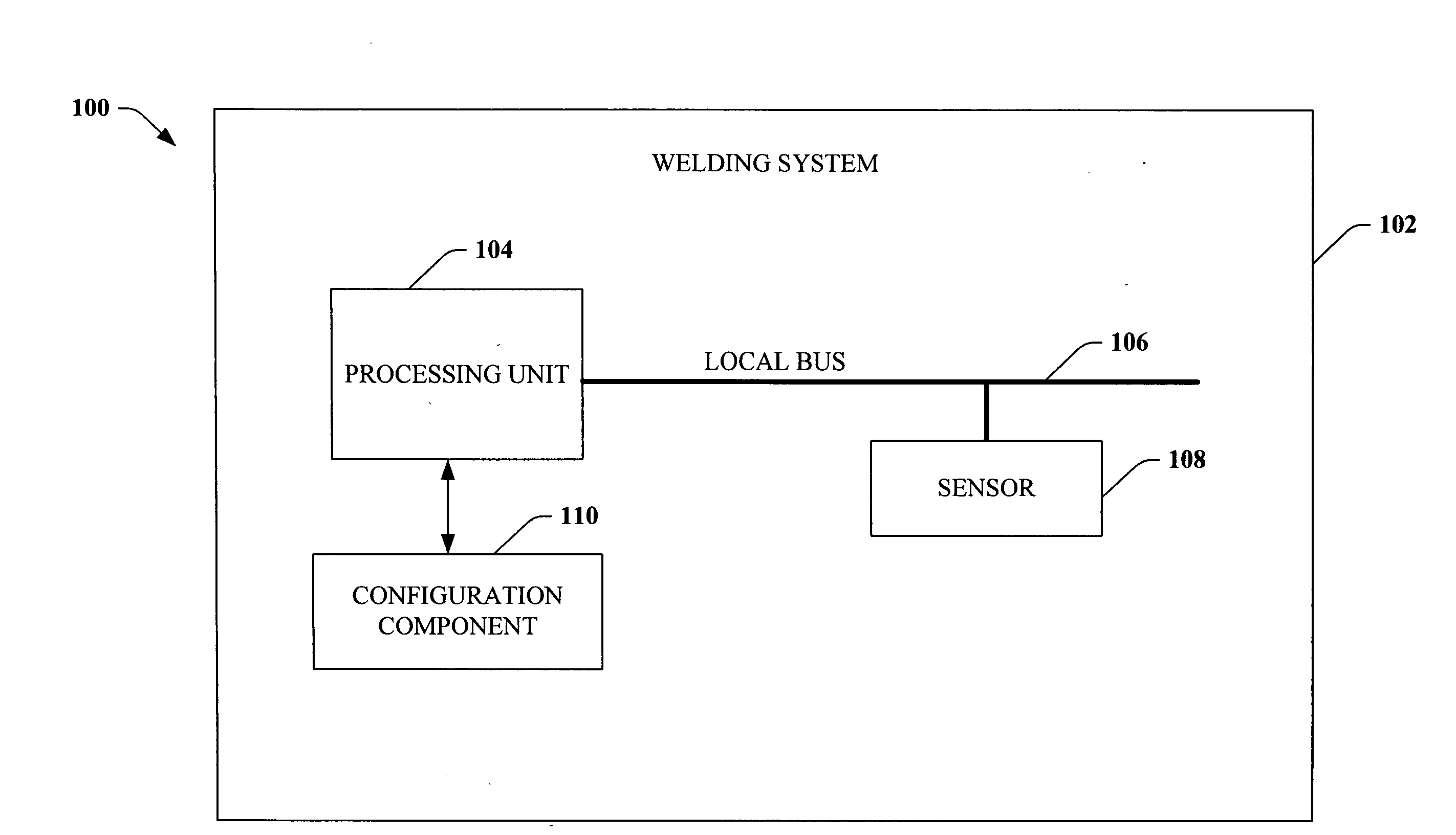
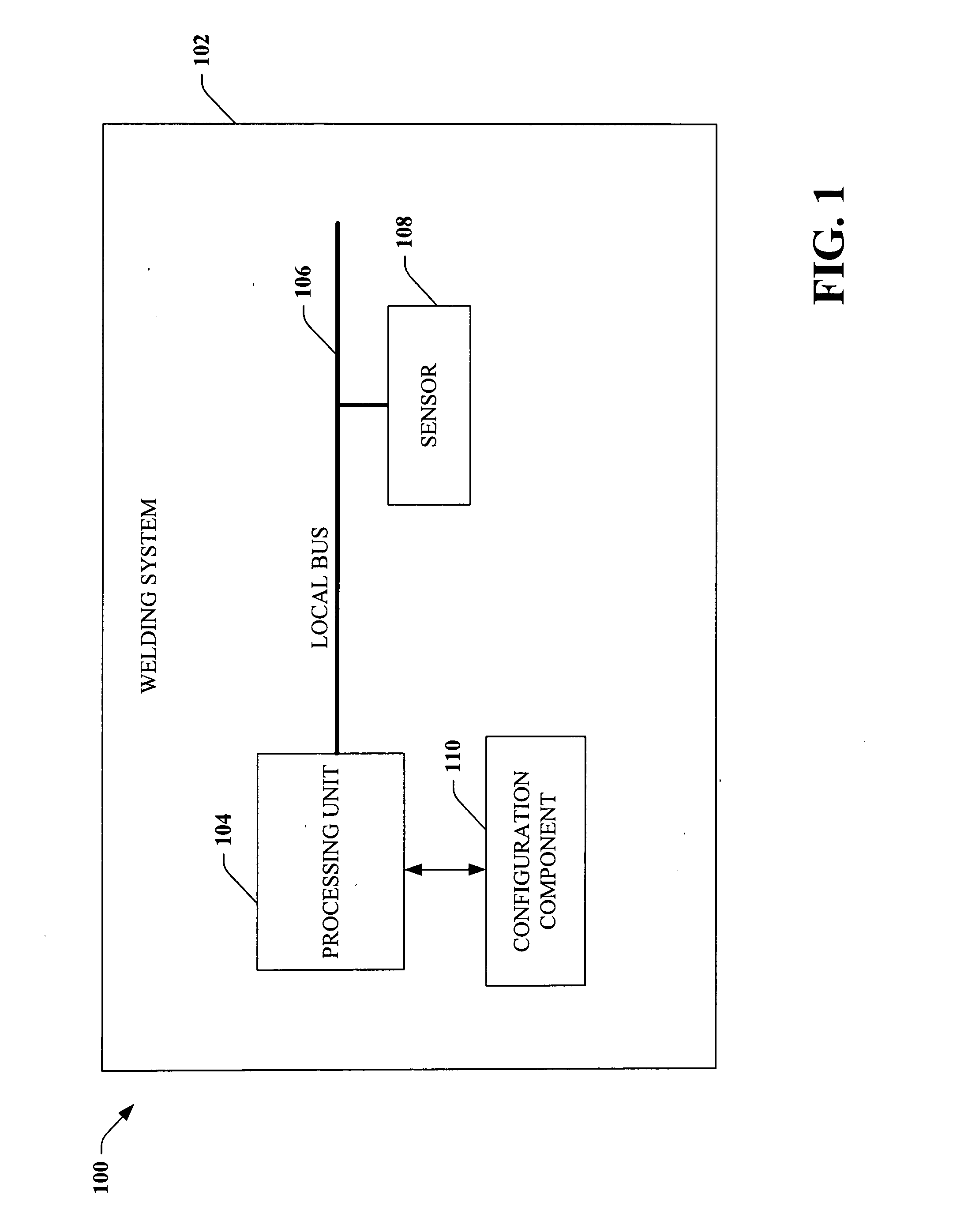
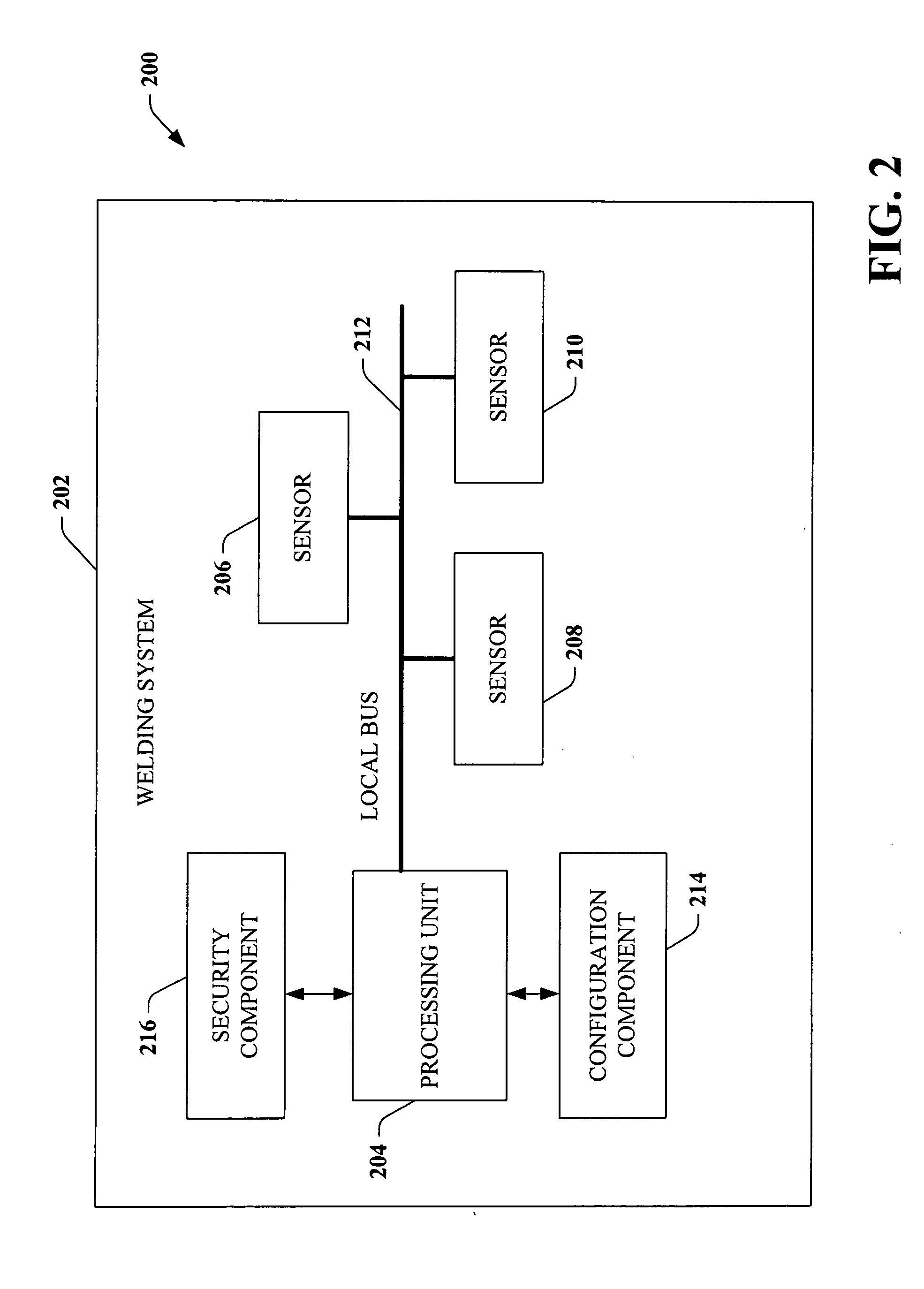
[0007] The subject invention relates to novel systems and/or methodologies for configuring a welding system in accordance with a newly added and/or recently removed sensor(s). In particular, one or more aspects of the subject invention mitigate deficiencies of conventional systems with respect to hard-wired sensors. In general, the subject invention relates to dynamically configuring a welding system upon detecting alteration of sensors upon a local bus, wherein such local bus is utilized for communications between welding devices (e.g., sensors, motors, . . . ) and a processing unit. The processing unit can be employed to control and/or monitor a welding process being undertaken within the welding system.
[0008] When one or more sensors are coupled to the local bus, a configuration component can detect such coupling and configure the welding system in accordance with the newly added sensor(s). Similarly, if one or more sensors are removed from the local bus, the configuration component can configure the welding system in accordance with the recently removed sensor(s). Thus, rather than requiring a technician to hard-wire sensors in relation to a welding unit, the subject invention enables dynamic additi

Problems solved by technology

Configuring disparate welding units with particular sensors, however, can be quite challenging, as sensors are often manufactured by different vendor(s) than vendor(s) that manufacture the welding units.
Applications associated with welding units, however, can be frequently subject to change, thereby rendering the sensor configuration ill-suited for a new application.
Such configuration is costly, as the welding system can be disabled for an extended period of time, thus adversely affecting manufacturing throughput.
Moreover, a skilled technician is required to effectuate any alterations made to sensors associated with a welding system, thereby increasing monetary costs.

Method used


Image

  • Integrating sensors over a digital link
  • Integrating sensors over a digital link
  • Integrating sensors over a digital link

Examples


Embodiment Construction

[0021] The subject invention is now described with reference to the drawings, wherein like reference numerals are used to refer to like elements throughout. In the following description, for purposes of explanation, numerous specific details are set forth in order to provide a thorough understanding of the subject invention. It may be evident, however, that the subject invention may be practiced without these specific details. In other instances, well-known structures and devices are shown in block diagram form in order to facilitate describing the subject invention.

[0022] As used in this application, the terms “component,”“handler,”“model,”“system,” and the like are intended to refer to a computer-related entity, either hardware, a combination of hardware and software, software, or software in execution. For example, a component may be, but is not limited to being, a process running on a processor, a processor, an object, an executable, a thread of execution, a program, a computer...


PUM

PropertyMeasurementUnit
Poweraaaaaaaaaa
Configurationaaaaaaaaaa

Abstract

A system that facilitates dynamic configuration of a welding system with respect to a sensor comprises a processing unit associated with the welding system. A configuration component facilitates configuring the welding system with respect to the sensor upon determining that the sensor is coupled to a local bus associated with the processing unit. A remote access component can facilitate remotely accessing the welding system, the configuration of the welding system alterable by way of the remote access component.

Description

TECHNICAL FIELD [0001] The subject invention relates generally to sensor configurations within a manufacturing environment, and more particularly to configuring a welding system in relation to one or more sensors. BACKGROUND OF THE INVENTION [0002] Welding systems reside at the core of the modem industrial age. From massive automobile assembly operations to automated manufacturing environments, these systems facilitate joining in ever more complicated manufacturing operations. One such example of a welding system includes an electric arc welding system. This may involve movement of a consumable electrode, for example, toward a work piece while current is passed through the electrode and across an arc developed between the electrode and the work piece. The electrode may be a non-consumable or consumable type, wherein portions of the electrode may be melted and deposited on the work piece. Often, hundreds or perhaps thousands of welders are employed to drive multiple aspects of a cons...

Claims


Application Information

Patent Timeline
IPC IPC(8): B23K9/095
CPCB23K9/095B23K11/25
Inventor HILLEN, EDWARD D.KAINEC, STEPHEN M.
Owner LINCOLN GLOBAL INC
Learn More