
Automatic gearbox with a hydraulically actuated shifting element

a technology of shifting element and automatic gearbox, which is applied in the direction of gearing, interlocking clutches, and hydraulically actuated brakes. it can solve the problems of comparatively high power loss, long reaction time, and perceived long time, and achieve the effect of appreciable time gain

Inactive Publication Date: 2006-07-27
ZF FRIEDRICHSHAFEN AG
View PDF7 Cites 14 Cited by
  • Summary
  • Abstract
  • Description
  • Claims
  • Application Information

AI Technical Summary

Benefits of technology

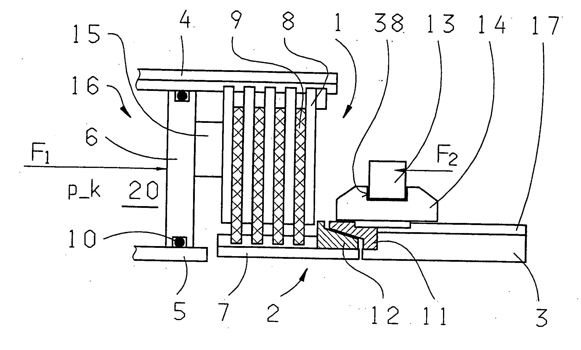
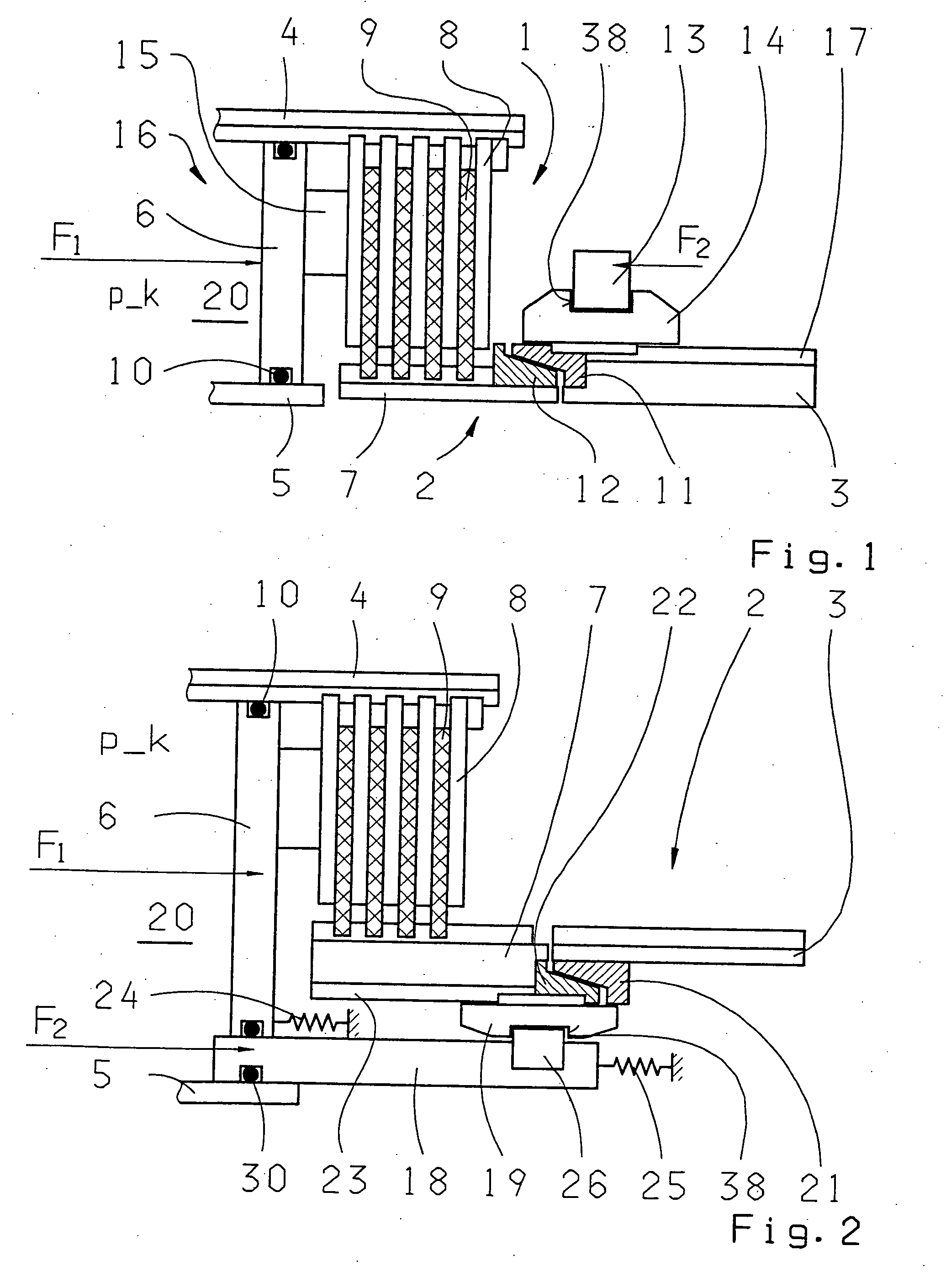
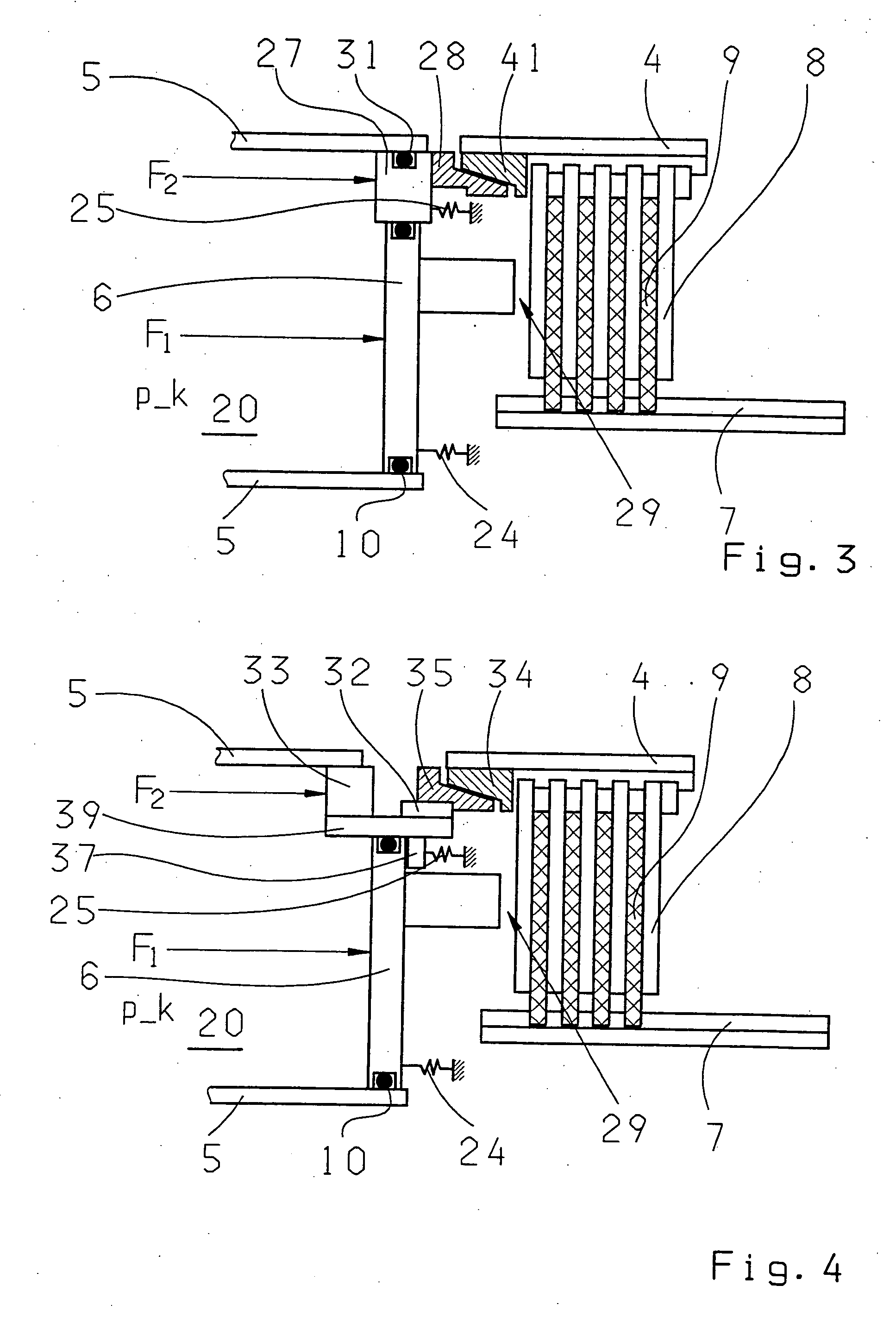
[0018] The invention is based on the recognition that actuation of the synchronization device of such a shifting element independently of the compression of the shifting element disks enables an appreciable time gain when carrying out a transmission ratio change process.
[0034] To leave free sufficient structural space and room for movement for the synchronization device component and for the locking device if provided, it can finally be provided that an axial projection directed away from the pressure space of the piston-cylinder arrangement is formed on the first actuation piston, by way of which the inner or outer disks of the disk clutch or disk brake, respectively, can be acted upon with the actuation force F1 of the first actuation piston.

Problems solved by technology

Such transmission shifting elements, however, besides certain advantages, also have the disadvantage of causing comparatively high power loss even when not engaged because of the relative rotation between the steel disks and lining disks.
However, this creates the disadvantage that owing to the force of the restoring spring the piston-cylinder arrangement has to be made larger, and when the actuation piston is acted upon by a clutch-closing pressure the actuation path corresponding to the air clearance first has to be covered in a pre-filling phase before the disks come into force-transferring engagement.
In typical automatic gearboxes it takes approximately 200 ms to cover the air clearance path, and this is perceived as a long time particularly by drivers of sports vehicles.
Especially in vehicles having automatic gearboxes with sequential shift systems, in which the transmission gears of the automatic gearbox can be engaged manually by means of a trip-switch, such shifting delays are complained of as slowness of the reaction time.
A disadvantage of this gearbox, however, is that the positive-lock clutch between the inner disk carrier of the disk brake and the planetary support of the planetary gearset can only be closed comfortably when the inner disk carrier and planetary support are rotating at the same speed.
In contrast, if there is a rotation speed difference between the inner disk carrier and the planetary support, the positive-lock clutch cannot be engaged or only so with high expenditure of force and at the same time high noise emission.
To minimize the force used and the noise emitted when the positive-lock clutch is closed, it is necessary for the inner disk carrier and the planetary support to be at rest, which distinctly limits the utility range of this system.
Namely, with both actuation arrangements, it is disadvantageous that in both a closing and an opening process the actuation piston for the disk clutch has to move through a comparatively large regulating distance, which is noticeable as a somewhat longer time required to carry out a transmission ratio change process in the gearbox.

Method used


Image

  • Automatic gearbox with a hydraulically actuated shifting element
  • Automatic gearbox with a hydraulically actuated shifting element
  • Automatic gearbox with a hydraulically actuated shifting element

Examples


Embodiment Construction

[0048] Fundamentally, the invention can be implemented with both transmission brakes and transmission clutches which are used as shifting elements in an automatic gearbox. In presenting example embodiments of the invention, however, only disk brakes will be shown since the structure of disk clutches constructed according to the invention differs only very little from these disk brakes. In the disk brakes, the outer and inner disk carriers rotate with a rotation speed relative to one another when the clutch is open, as is known. When the clutch is closed, the rotation speeds are equalized. However, the restoring springs for the automatic opening of the clutch after the decrease of a clutch actuation pressure do not in this case rest against a static transmission component (when a rotating bearing relative to a component fixed to the housing is present) but rather, against correspondingly rotating components. Thus, the pressure pistons and the restoring springs associated with them ro...


PUM


Abstract

An automatic gearbox for a vehicle with at least one hydraulically actuated shifting element made as a transmission brake or transmission clutch. The shifting element has an inner disk carrier and an outer disk carrier where inner disks and outer disks are arranged rotationally fixed but axially displaceably. The disks are arranged in alternating sequence one after the other to form a disk pack which can be acted upon by an actuator with an axial actuation force to close the shifting element, and in which one disk carrier is connected to non-rotating or rotating gearbox components and the other disk carrier can be connected via a synchronization device to rotating gearbox components. To reduce the shifting time that can be achieved with such a gearbox in carrying out a transmission ratio change process, a synchronization device can be actuated by way of a second actuator of its own.

Description

[0001] This application is a national stage completion of PCT / EP2004 / 007139 filed Jul. 1, 2004 which claims priority from German Application Serial No. 103 31 370.2 filed Jul. 11, 2003.FIELD OF THE INVENTION [0002] The invention concerns an automatic gearbox with at least one hydraulically actuated shifting element formed as a transmission brake or transmission clutch. BACKGROUND OF THE INVENTION [0003] It is known that in automatic variable-speed gearboxes with planetary gearset systems, disk clutches and disk brakes are used for engaging the individual gears. These are actuated by pressure medium operated piston-cylinder arrangements whose pressure medium supply is controlled by a control and regulation unit. [0004] Such transmission shifting elements, however, besides certain advantages, also have the disadvantage of causing comparatively high power loss even when not engaged because of the relative rotation between the steel disks and lining disks. This power loss can only be re...

Claims


Application Information

Patent Timeline
Patent Type & Authority Applications(United States)
IPC IPC(8): F16D23/04F16D25/10F16D55/40F16D67/00F16D67/04F16H3/12F16H61/04F16H63/30
CPCF16D55/40F16D67/04F16H3/12F16H61/0403F16H63/3026F16H2306/48
Inventor SCHMIDT, THILOPOPP, CHRISTIAN
Owner ZF FRIEDRICHSHAFEN AG
Learn More