
Vehicular air-conditioning system

a technology of air-conditioning system and vehicle, which is applied in the direction of refrigeration components, transportation and packaging, light and heating equipment, etc., can solve the problems of excessive electric power consumption and the inability of the engine to drive the compressor, and achieve the effect of preventing excessive electric power consumption

Inactive Publication Date: 2006-07-27
HONDA MOTOR CO LTD
View PDF17 Cites 10 Cited by
  • Summary
  • Abstract
  • Description
  • Claims
  • Application Information

AI Technical Summary

Benefits of technology

[0006] It is therefore an object of the present invention to provide a vehicular air-conditioning system which is designed to prevent an electric motor from being driven under an unnecessary condition or at an unnecessarily high rotational speed while outside air is being introduced into the air-conditioning system with an engine placed in an idling-stopped condition, to thereby prevent excessive consumption of electric power.
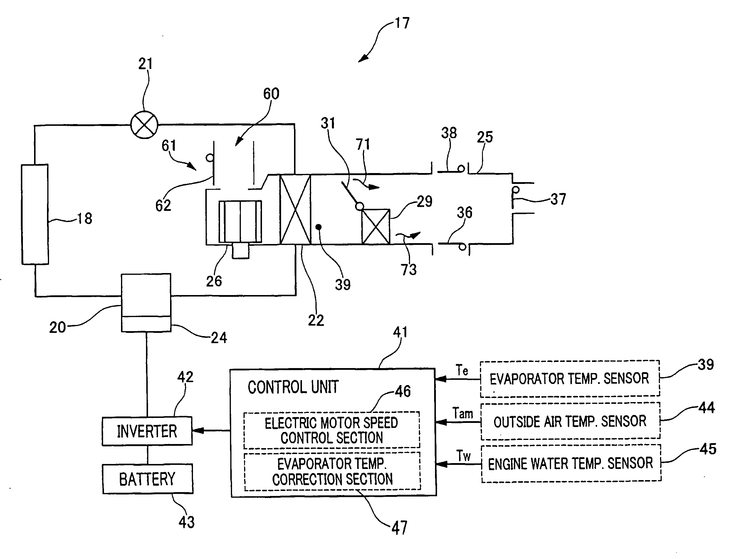
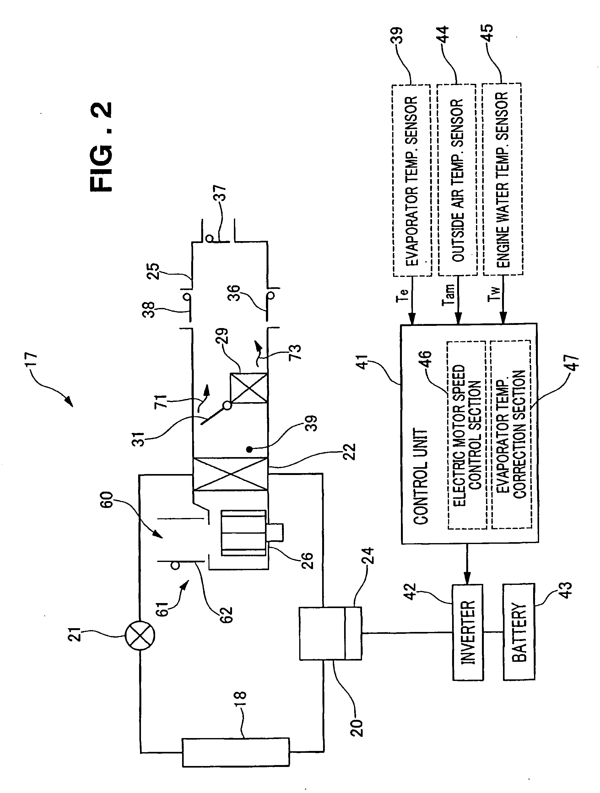
[0009] When idling of the engine is stopped while the outside air is being introduced into the air-conditioning system, influences of the temperature of the outside air and the temperature of the engine-cooling water, which can cause undesirable increase in temperature at the outlet of the evaporator, can be removed from the temperature, detected by the evaporator temperature sensor, to provide appropriately low temperature for use as the temperature at the outlet of the evaporator. Thus, it becomes possible to prevent the electric motor from being driven under the inappropriate condition or at the higher speed than is necessary when the outside air is introduced into the air-conditioning system while the engine stops. This can eliminate concern over excessive consumption of electric power.

Problems solved by technology

In such a vehicle, the engine cannot drive the compressor during its idling-stopped state.
In this instance, the electric motor whose speed is controlled in correspondence with a temperature of the air at the outlet of the evaporator can be driven under an unnecessary condition or at an unnecessarily high speed due to the greater air temperature at the outlet of the evaporator, thus resulting in excessive consumption of electric power.

Method used


Image

  • Vehicular air-conditioning system
  • Vehicular air-conditioning system
  • Vehicular air-conditioning system

Examples


Embodiment Construction

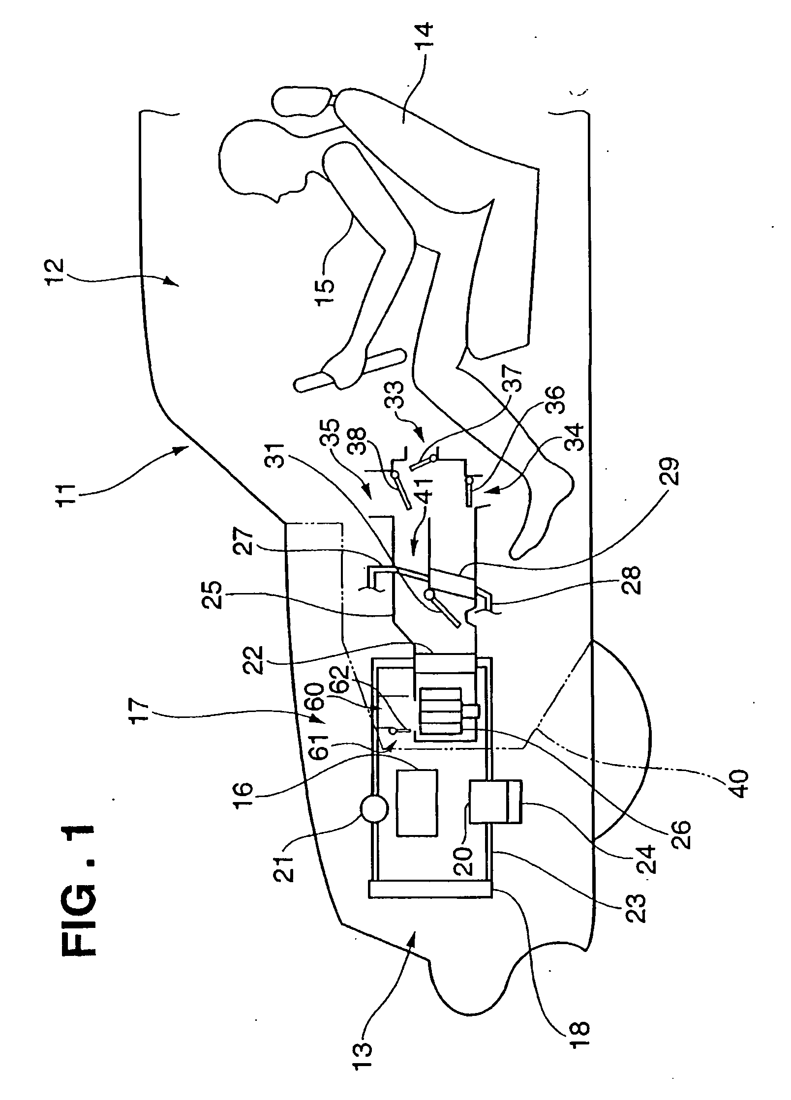
[0021] Referring to FIG. 1, there are shown a passenger compartment 12 and an engine compartment 13 of an automobile 11. A driver 15 sits on a seat 14 within the passenger compartment 12. An engine 16 is disposed within the engine compartment 13. The engine 16 outputs motive power to be transmitted by a transmitting mechanism (not shown).

[0022] The automobile 11 includes an idling-stop system, not shown, for temporarily stopping idling of the engine 16 when the automobile 11 is place in a state which satisfies predetermined stop conditions.

[0023] Arrangement of an air conditioning system 17 will be described now. A condenser 18 and a condenser fan (not shown) are disposed forwardly of the engine 16. Connected through refrigerant pipes 23 to the condenser 18 are a compressor 20 and an expansion valve 21. Connected through refrigerant pipes 23 to the compressor 20 and the expansion valve 21 is an evaporator 22. The condenser 18, the compressor 20, the expansion valve 21, the evapora...


PUM


Abstract

An air-conditioning system for a vehicle having an engine adapted to stop idling on predetermined stop conditions of the vehicle, which system comprises an electric motor for driving a refrigerant compressor when the engine idling is stopped, motor speed control means for controlling the speed of the motor in correspondence with an evaporator outlet temperature, and evaporator temperature correction means for, when the engine idling is stopped while outside air is being introduced, correcting the evaporator outlet temperature to a lower temperature in correspondence with a temperature of the outside air and a temperature of engine cooling water.

Description

FIELD OF THE INVENTION [0001] The present invention relates generally to an air-conditioning system and, more particularly, to an air-conditioning system for a vehicle carrying an idling-stop system for temporarily stopping idling of an engine of the vehicle. BACKGROUND OF THE INVENTION [0002] Conventional vehicular air-conditioning systems typically use a vapor-compression refrigeration system, which includes a closed circuit (refrigeration cycle) having a compressor, a condenser, an expansion valve and an evaporator. Refrigerant circulates through the closed circuit. The refrigerant vaporizes as it absorbs heat from air within a passenger compartment of a vehicle to thereby cool the air. [0003] More specifically, the refrigerant in a liquid state passes through an expansion valve where the refrigerant undergoes adiabatic expansion and decreases in pressure and temperature. Thereafter, the refrigerant in the form of mist enters an evaporator and vaporizes upon absorbing heat from a...

Claims


Application Information

Patent Timeline
Patent Type & Authority Applications(United States)
IPC IPC(8): F25B27/00
CPCB60H1/3208B60H1/3222B60H2001/3263B60H2001/3272F25B49/025F25B2500/19F25B2700/2106F25B2700/21173
Inventor FUJIKI, TSUTOMUYASUNO, SHINJI
Owner HONDA MOTOR CO LTD
Learn More