Sensor device for automatic door assembly

Inactive Publication Date: 2006-07-27
OPTEX CO LTD
View PDF11 Cites 30 Cited by
  • Summary
  • Abstract
  • Description
  • Claims
  • Application Information

AI Technical Summary

Benefits of technology

[0008] In view of the foregoing, the present invention has been devised to substantially alleviate the foregoing problems and inconveniences inherent in the prior art sensor systems and is intended to provide a sensor device for the automatic door assembly, which is compact and simple and can be mounted and dismounted easily to be a support member, and further can be assembled at a reduced cost and be effective to secure the safety in the doorway vicinity.
[0010] According to the present invention, since the activation sensor and the safety sensor are supported in the relation overlapping one above the other in a direction conforming to the fixing direction in which they are fixed to the mounting member, any existing mounting structure currently employed to support the activation sensor can be employed with the safety sensor mounted over the activation sensor so that the safety in the doorway vicinity can be secured through the safety sensor. Accordingly, mounting and dismounting of the sensor assembly can be effected by a simple one direction operation or movement of the mounting member, and further, the sensor device of the present invention is effective to secure the safety in the doorway vicinity with a compact and simplified structure and at an advantageously reduced cost.
[0011] Preferably, the mounting member referred to above is made up of a first mounting piece for fixing the activation sensor to the safety sensor in the overlapped relation and a second mounting piece for fixing the safety sensor to the support member. In this case, since the activation sensor is fixed to the safety sensor through the first mounting piece, which may be an existing mounting piece, and the safety sensor is fixed to the support member through the second mounting piece together with the activation sensor, the first and second mounting pieces can be made compact.
[0012] The activation sensor referred to above may preferably include a activation sensor main body and a activation sensor cover and, on the other hand, the safety sensor may include a safety sensor main body having a support projection for supporting the activation sensor main body and a safety sensor cover having an opening defined by an inner peripheral face engageable with an outer peripheral surface of the support projection, with a portion of the safety sensor cover overlapping the activation sensor cover in the direction in which the activation sensor is fixed. These design features are particularly advantageous in that engagement of the opening of the safety sensor cover over the support projection of the safety sensor main body is effective to provide a dust tight effect to the external environment. Also, since the activation sensor cover is fixed to that portion of the safety sensor cover in the overlapped relation, an uncalled-for removal of the safety sensor cover by an unauthorized person can be effectively prevented. That portion of the safety cover may be a seating protuberance formed on the inner peripheral face of the opening in the safety sensor cover.
[0013] Also preferably, the activation sensor and the safety sensor may be fixed in an overlapped relation with each other to the support member through a common mounting member. In this case, the activation sensor and the safety sensor can be fixed to the support member through the common mounting member and accordingly, mounting and dismounting of the sensor device of the present invention can be further facilitated.

Problems solved by technology

It has, however, been found that since the MW (microwave) sensor makes use of, for example, the Doppler effect, the MW sensor is incapable of detecting a still object and, therefore, it is quite often that a person trying to move past the door assembly may be jammed between a sliding door and a pillar or between sliding doors once he or she stands still in the doorway.
However, the system in which, in order to secure the safety in the doorway vicinity, the photosensor is employed separately in addition to the MW sensor such as hitherto practiced in the art, has a problem in that since the photosensor is installed using separate support members, the sensor system as a whole tends to become bulky and requires a complicated electric wiring system.
Also, replacement of the MW sensor with the sensor device having the combined function of the MW sensor and the photosensor tends to result in increase of the cost.

Method used


Image

  • Sensor device for automatic door assembly
  • Sensor device for automatic door assembly
  • Sensor device for automatic door assembly

Examples


first embodiment

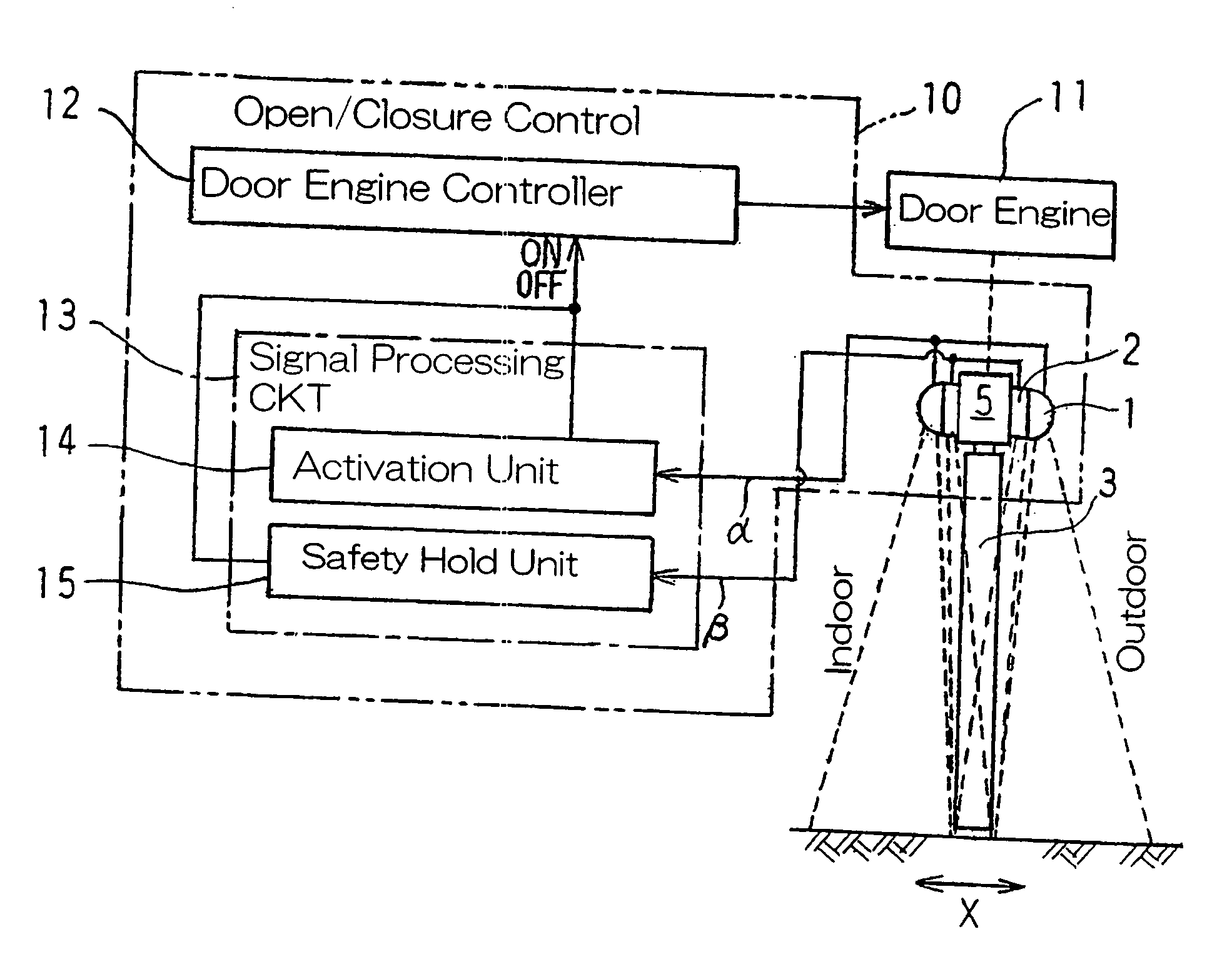
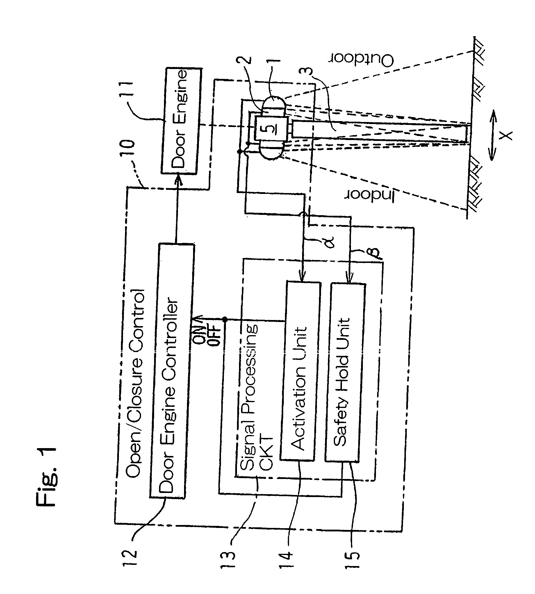
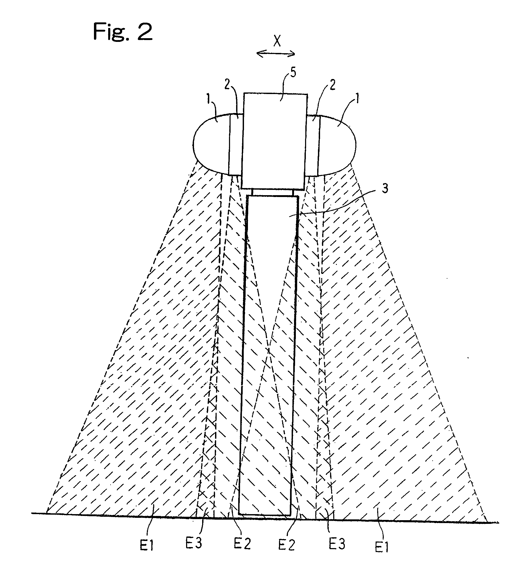
[0027] The automatic door sensor device according to the present invention is shown in a side representation in FIG. 2. As hereinabove described, this automatic door sensor device includes the activation sensor 1 and the safety sensor 2. It is to be noted that in FIG. 2, the automatic door sensor device is shown as employed in two in number, one assigned to detect a person ready to enter a building past the door assembly and the other to detect a person ready to go out of the building past the door assembly. However, since the automatic door sensor devices assigned to detect persons ready to enter and go out of the building past the door assembly, respectively, are of a substantially identical construction and since the present invention in a broad aspect thereof works satisfactorily with the sole automatic door sensor device, reference will be made in this specification to only one of the automatic door sensor devices.

[0028] The activation sensor 1 referred to above and forming a p...

second embodiment

[0051] Referring now to FIG. 6, showing a side view of the sensor device, as is the case with those in the previously described embodiment, the MW sensor 1 is of a generally hemispherical configuration having its base representing a substantially oval shape when viewed from front and the AIR sensor 2A is of a generally flattened configuration. However, in the second embodiment, as best shown in a front elevational view in FIG. 7, the AIR sensor 2A is of a size substantially identical with that of the MW sensor 1 when viewed from front and, hence, the AIR sensor 2 has an outer periphery held in flush with that of the base of the MW sensor 1.

[0052] The existing MW sensor 1 is of a structure in which the base support la thereof has screw insertion throughholes 8 defined therein for the passage of mounting pieces (screw members) used to secure the MW sensor 1 to the transom 5. In correspondence therewith, the AIR sensor 2A has corresponding screw insertion throughholes 59 defined therei...


PUM


Abstract

To provide a compact sensor device for the automatic door assembly, which can be mounted and dismounted easily to a support member and be effective to secure the safety in the doorway vicinity, a activation sensor (1) for opening a door (3) and a safety sensor (2) for keeping the door (3) open are supported in a fashion overlapped one above the other in a direction conforming to the direction in which they are secured to a support member (5).

Description

BACKGROUND OF THE INVENTION [0001] 1. Field of the Invention [0002] The present invention relates to a sensor device for an automatic door assembly, which is operable to output in response to detection of a human body, an output signal necessary to control selective opening and closure of the automatic door assembly. [0003] 2. Description of the Prior Art [0004] It is generally known to use a sensor device such as, for example, a photosensor so that in response to detection of a human body moving past a door assembly, selective opening and closure of the automatic door assembly can be controlled. See, for example, the Japanese Laid-open Patent Publication No. 11-311060. For the photosensor, either an infrared reflection type switch or a pyroelectric switch is generally largely employed. [0005] In the case where the automatic door assembly is installed in the environment in which it tends to be exposed to the weather or airborne dust and dirt, a radar sensor (microwave sensor) operab...

Claims


Application Information

Patent Timeline
IPC IPC(8): E05F15/02G08B13/18H02P29/04
CPCE05Y2600/45E05Y2900/132E05F2015/434E05F15/73E05F15/43
Inventor IMAI, TAKASHISHIMADA, HIROFUMI
Owner OPTEX CO LTD
Why Eureka
Try Eureka