Eureka AIR delivers breakthrough ideas for toughest innovation challenges, trusted by R&D personnel around the world.

System verification test using a behavior model

a behavior model and system verification technology, applied in the field of system verification test, can solve the problems of manual regression testing, high labor intensity, time-consuming, error-prone, etc., and achieve the effect of fewer test escapes and better test coverag

Active Publication Date: 2006-07-20
SPIRENT COMM
View PDF23 Cites 21 Cited by
  • Summary
  • Abstract
  • Description
  • Claims
  • Application Information

AI Technical Summary

Benefits of technology

[0014] Since the system verification system of the present invention is an automated system that can automatically generate the behavior model based on the actions and corresponding reactions captured from one or more runs of a test case, the labor involved in writing, testing, and maintaining scripts in SVT is eliminated. At the same time, the scriptless automated SVT system of the present invention results in better test coverage and fewer test escapes (“false positives”).

Problems solved by technology

The disadvantage of conventional manual SVT is that it requires regression testing to be done manually, i.e., manually repeating the test cases when the SUT has changed, typically because of a new build, new release, or changes in the SUT's hardware or software.
Regression testing using conventional manual SVT is labor-intensive, time-consuming, and error-prone, because there is no automation involved.
However, because the human labor involved in designing a script that can execute a test case, testing the script to make sure that it produces no false-negatives and no false-positives, and modifying the scripts as necessary when the script has reported a false-negative failure are significant, the benefit from test automation comes only after the test case is executed many times. A lot of times, intense human labor is required to design a script for executing a test case.

Method used


Image

  • System verification test using a behavior model
  • System verification test using a behavior model
  • System verification test using a behavior model

Examples


Embodiment Construction

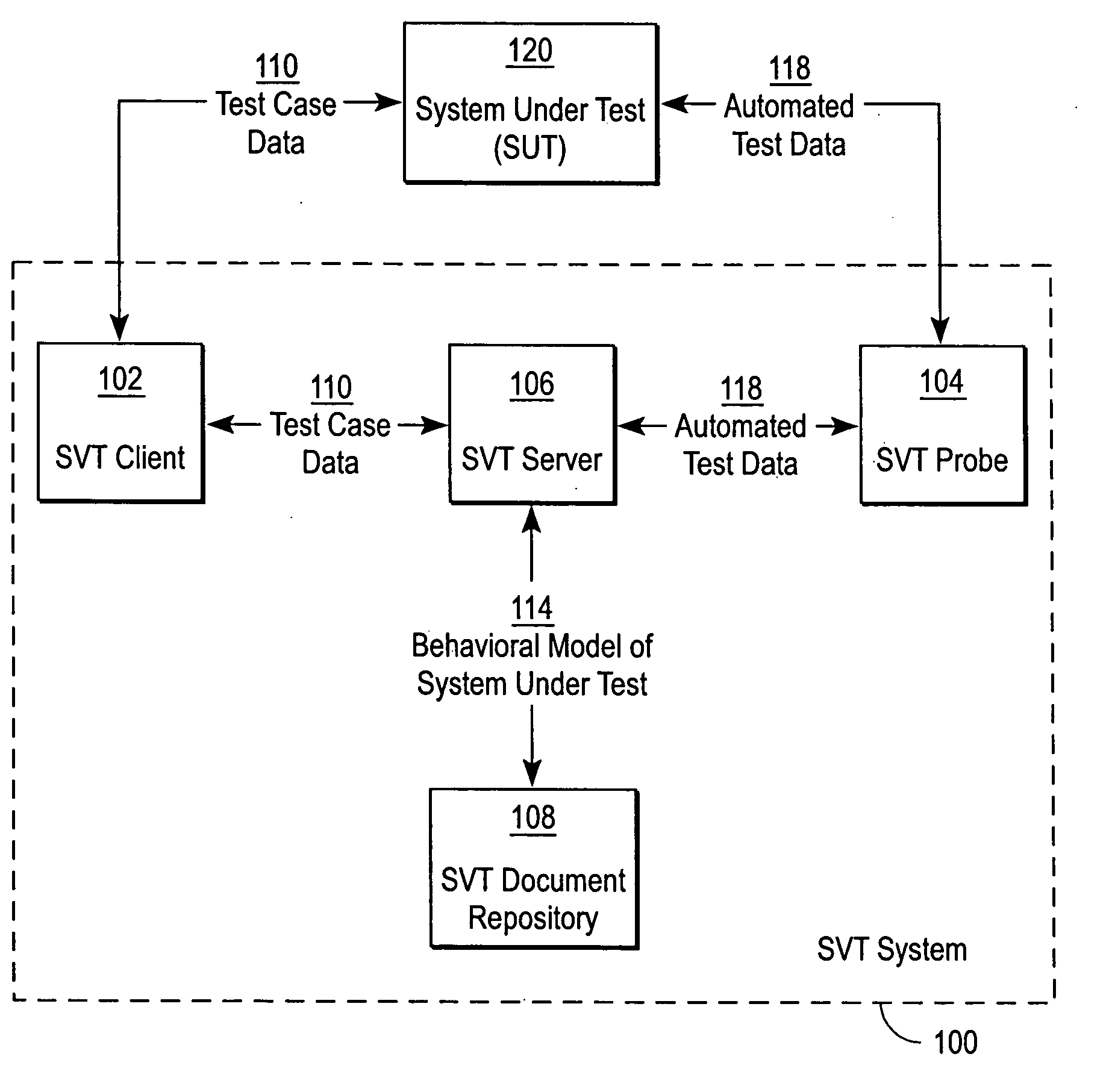
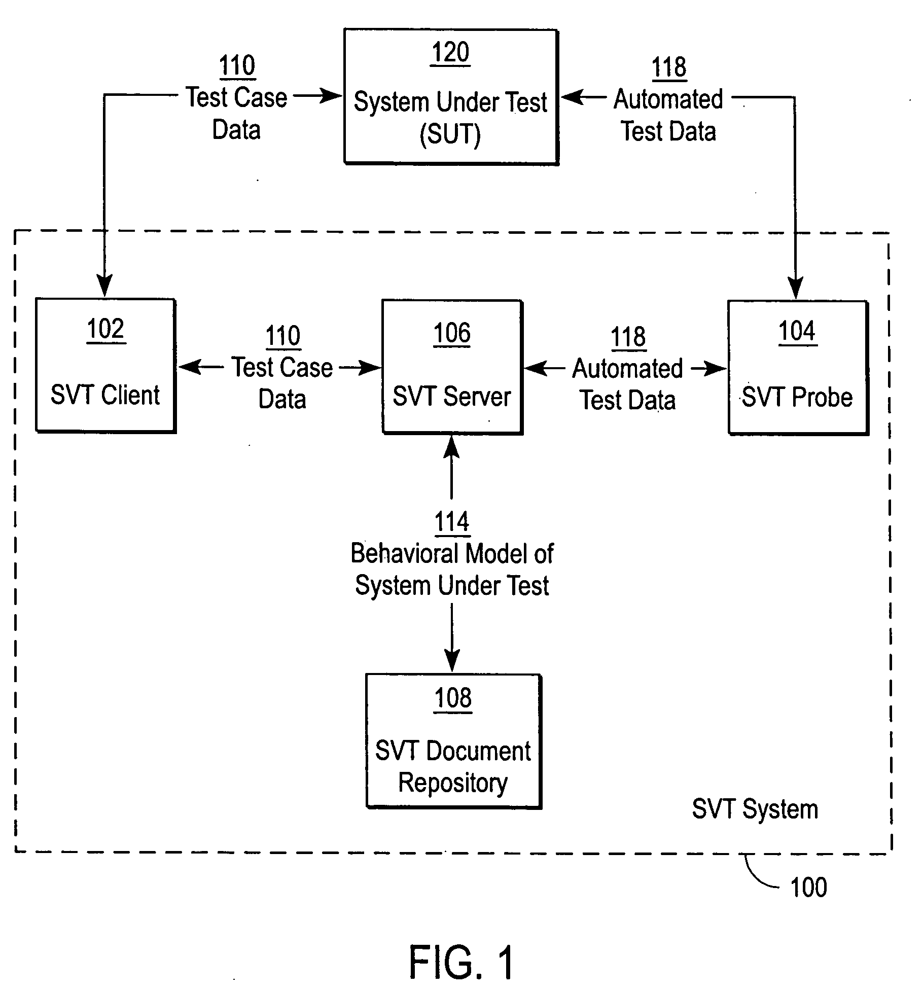
[0026]FIG. 1 is a block diagram illustrating the architecture of the System Verification Test (SVT) system 100 according to one embodiment of the present invention. The SVT system 100 verifies the functionalities of, and assures the quality of, the System Under Test (SUT) 120 according to the SVT process of the present invention. In one embodiment, the SVT system 100 includes an SVT server 106, an SVT client 102, an SVT probe 104, and an SVT document repository 108. The SVT server 106, SVT client 102, and the SVT probe 104 may be separate computers operating within the SVT system 100, and the SVT document repository 108 may be a database running on a separate database server or can also be part of the SVT server 106 itself. The SUT 120 may be any type of hardware devices, such as a computer, a networking device, a router, etc., or can also be computer software running on a computer.

[0027] The SVT client 102 captures data 110 while a test case is performed on the SUT 120. For exampl...


PUM


Abstract

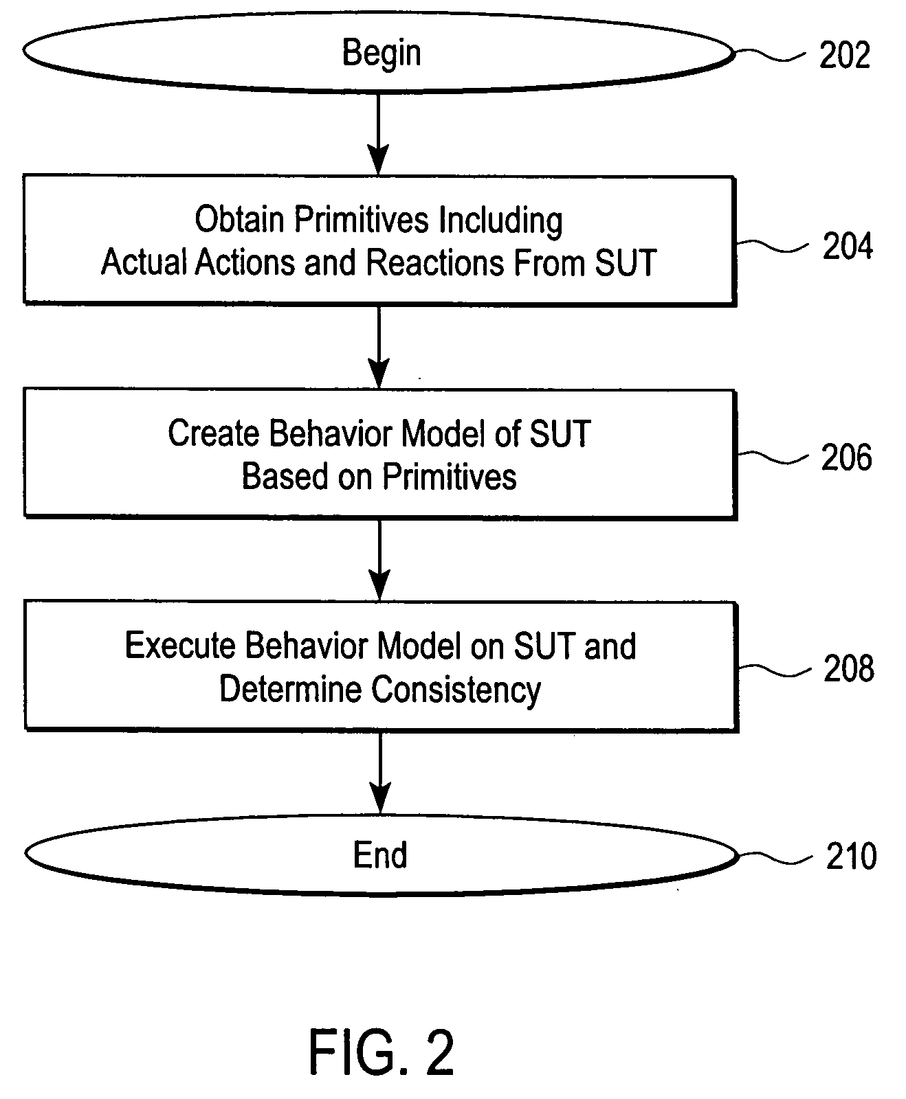
The present invention provides a system verification system that automatically generates a behavior model modeling the system under test in terms of actions of a test case and a range of expected reactions corresponding to those actions. In this regard, the system verification system obtains a set of actions and individual reactions corresponding to the actions from a plurality of runs of a test case for the system under test, and automatically generates the behavior model representing the system under test in terms of the set of actions and a range of expected reactions each range corresponding one of the actions. The range of expected reactions generalizes and includes all or most of the individual reactions corresponding to said one of the actions.

Description

TECHNICAL FIELD [0001] The present invention relates to system verification test (SVT) and, more specifically, to system verification test using a behavior model representative of the range of expected reactions from the System Under Test (SUT) corresponding to actions to the SUT. BACKGROUND OF THE INVENTION [0002] Most systems, whether it is a hardware system or a software system, requires quality assurance (QA) and system verification tests (SVT) before it is released for actual use by the public. Conventional methods of SVT include convention manual SVT and conventional automated SVT. [0003] The conventional manual SVT process typically involves the steps of (i) gaining an understanding of the feature to be tested on the SUT, (ii) designing one or more test cases to validate the features, (iii) executing the test case(s) manually, and (iv) analyzing the results of the executed test case(s). Obviously, the goal is to verify that the SUT meets the requirements for how a given featu...

Claims


Application Information

Patent Timeline
Patent Type & Authority Applications(United States)
IPC IPC(8): G06F17/00
CPCG06F11/263
Inventor DUFFIE, PAUL KINGSTONHORNBERGER, PATRICKHUBBARD, CARLOKAZAKI, SATOMISINGH, PAWAN
Owner SPIRENT COMM
Why Eureka
Eureka Blog
Learn More