Horizontal axis wind turbine

a wind turbine and horizontal axis technology, applied in the direction of liquid fuel engines, vessel construction, marine propulsion, etc., can solve the problems of difficulty in correcting the angle once set, and achieve the effect of easy change after installation and relatively easy installation

Inactive Publication Date: 2006-07-20
SUBARU CORP
View PDF4 Cites 32 Cited by
  • Summary
  • Abstract
  • Description
  • Claims
  • Application Information

AI Technical Summary

Benefits of technology

[0008] An object of the invention is to provide a horizontal axis wind turbine that is not complicated in installation work and relatively flexible in correction after installation with respect to controlling an azimuth angle and a tilt angle according to a change of wind direction.
[0010] Accordingly, because the change of pitch angle of the blades and the reverse in the rotating direction of the rotor can be performed without turning movement of a nacelle which was required by the above-described conventional example, installation work is not complicated due to omission of work for rotating the nacelle, and correction after installation becomes easier. As a result, the cost for maintenance can be cut down.
[0011] Preferably, the horizontal axis wind turbine comprises: a nacelle to support the rotor; a tower head which the nacelle is mounted on and comprises a rail with a circular or arc shape thereon; and a roller to support the nacelle, which is movable on and guided by the rail, to control an azimuth direction of the wind turbine. In the horizontal axis wind turbine, each roller is moved on the rail with a circular or arc shape, in a limited range to correspond to the change of wind direction in the range, which allows the wind turbine to be adjusted within a narrow range for the wind direction in the azimuth-angle direction.
[0013] According to such a horizontal axis wind turbine, the inclination angle can be controlled by extending and retracting the actuators without producing a special cam track which was required by the above-described conventional example, therefore installation cost can be reduced including omission of work to lift a large cam, and further a horizontal axis wind turbine more precisely facing the wind direction can be implemented.
[0021] The horizontal axis wind turbine according to the invention allows the pitch angle of blades to be changed and the rotating direction of the rotor to be reversed when the wind turbine is fixed at a place where the wind direction is almost constant as for the seasons, or as in a coast side or a mountain side where a wind from the sea or an upflow wind blows in the daytime and a land wind or a downflow wind blows at night. Further, when the wind turbine is installed at a place where wind directions are changeable, in addition to the above-described changes of the pitch angle and the reverse of rotation, the wind turbine follows the azimuth direction of a wind using the rails and the rollers rotatably moving thereon, and controls the inclination angle by up-and-down control of the actuators to coincide with the wind direction. Accordingly, the wind turbine of the invention has advantages in that installation can be relatively easier and the change after the installation can be also easier.

Problems solved by technology

According to such a structure, the cam tracks have to be produced having different values of tilt angles correlative to azimuth angles for every installing position, and further a difficulty occurs in work for correcting the angle once set.

Method used


Image

  • Horizontal axis wind turbine
  • Horizontal axis wind turbine
  • Horizontal axis wind turbine

Examples


first embodiment

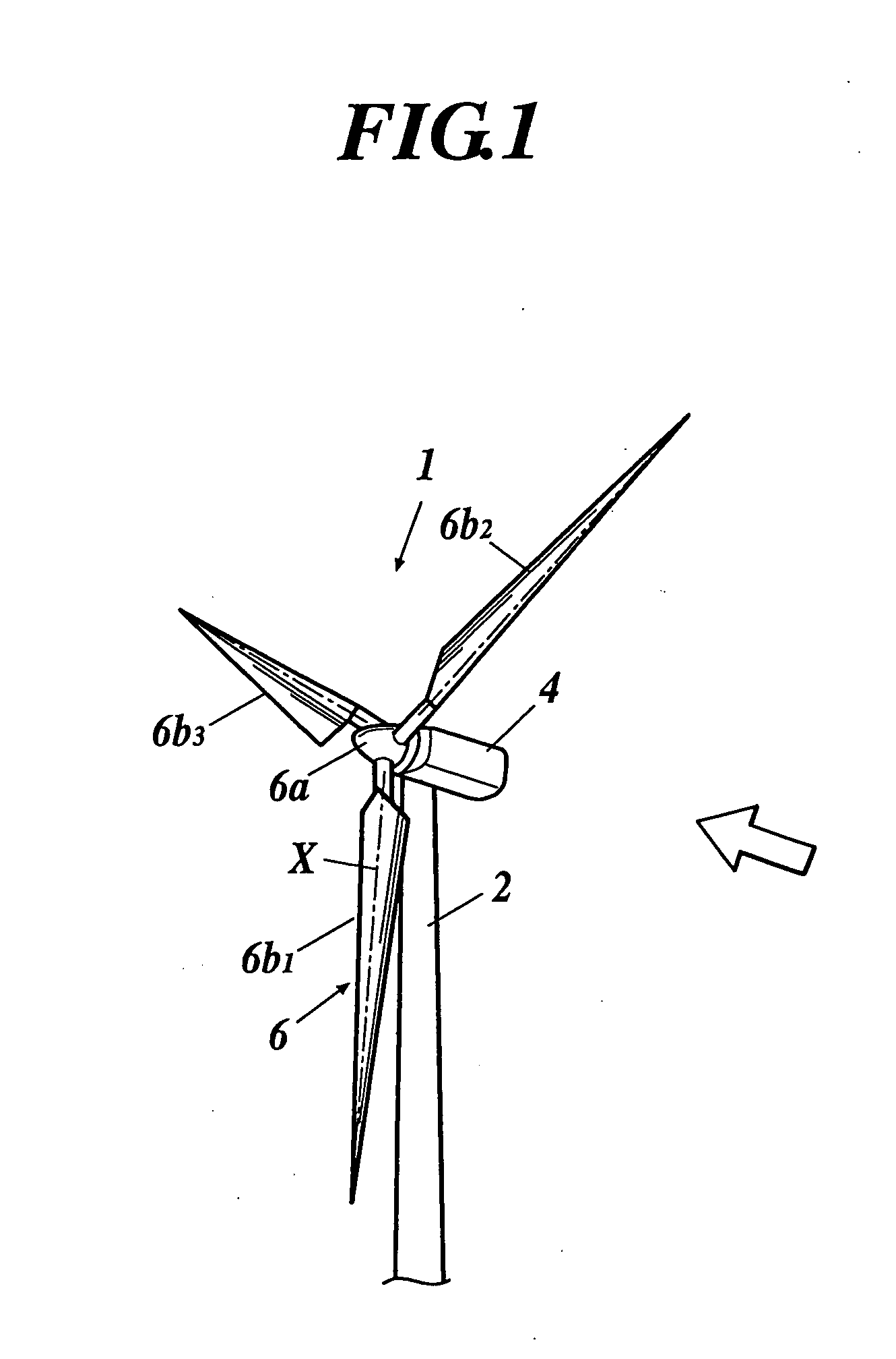
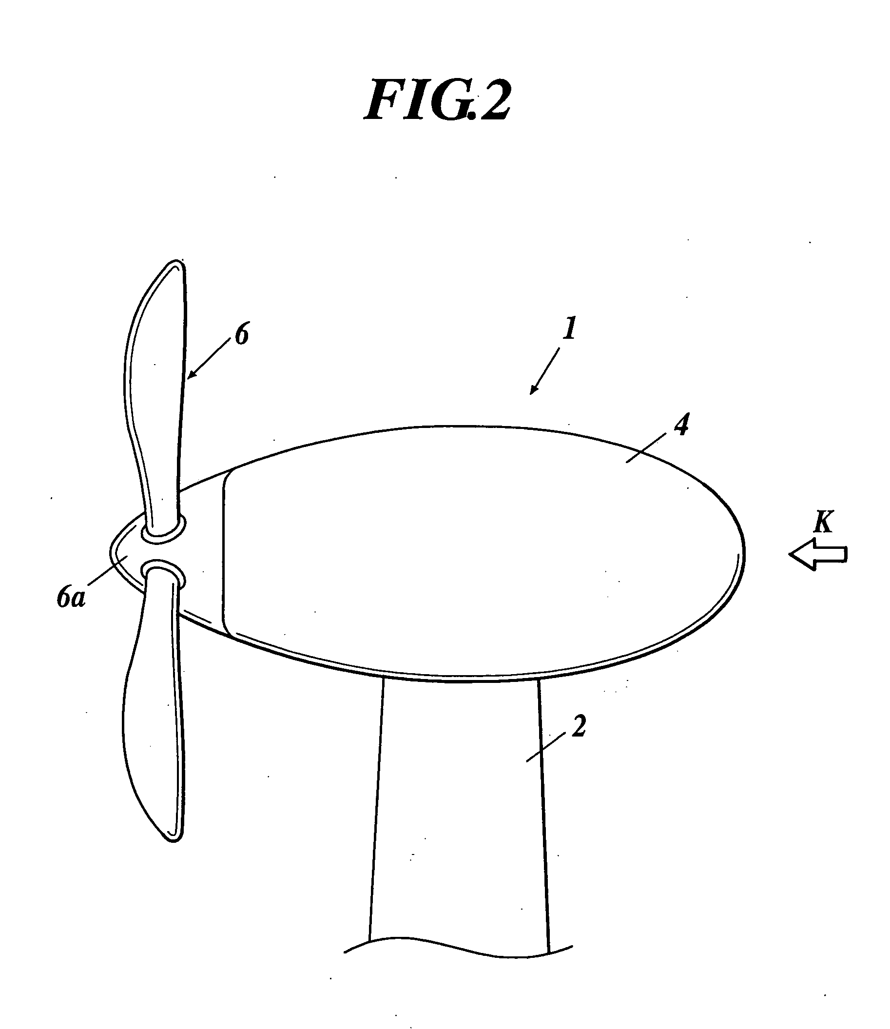
[0029] A horizontal axis wind turbine according to the invention will be explained with reference to FIGS. 1 and 2. The wind turbine will be explained by using a downwind horizontal axis wind turbine 1 as shown in FIG. 2.

[0030] Such a horizontal axis wind turbine 1 includes a tower 2 placed on the ground, an approximately cylindrical nacelle 4 directly fixed to the tower 2, a rotor shaft (not shown) rotatably supported to the nacelle 4, a hub 6a fixed to the rotor shaft, and a rotor 6 having three blades 6b1-6b3 in the embodiment, each blade attached to the hub 6a so that its pitch angle is changeable. Each of the blades 6b1-6b3 is attached to the hub 6a so as to be perpendicular to the rotor shaft.

[0031] Regarding the change of the pitch angle in the horizontal axis wind turbine 1, each pitch angle of the blades 6b1-6b3 is independently changeable, though not shown particularly. For the blade 6b1, for example, the base end thereof is attached to a ring gear which is rotatably supp...

second embodiment

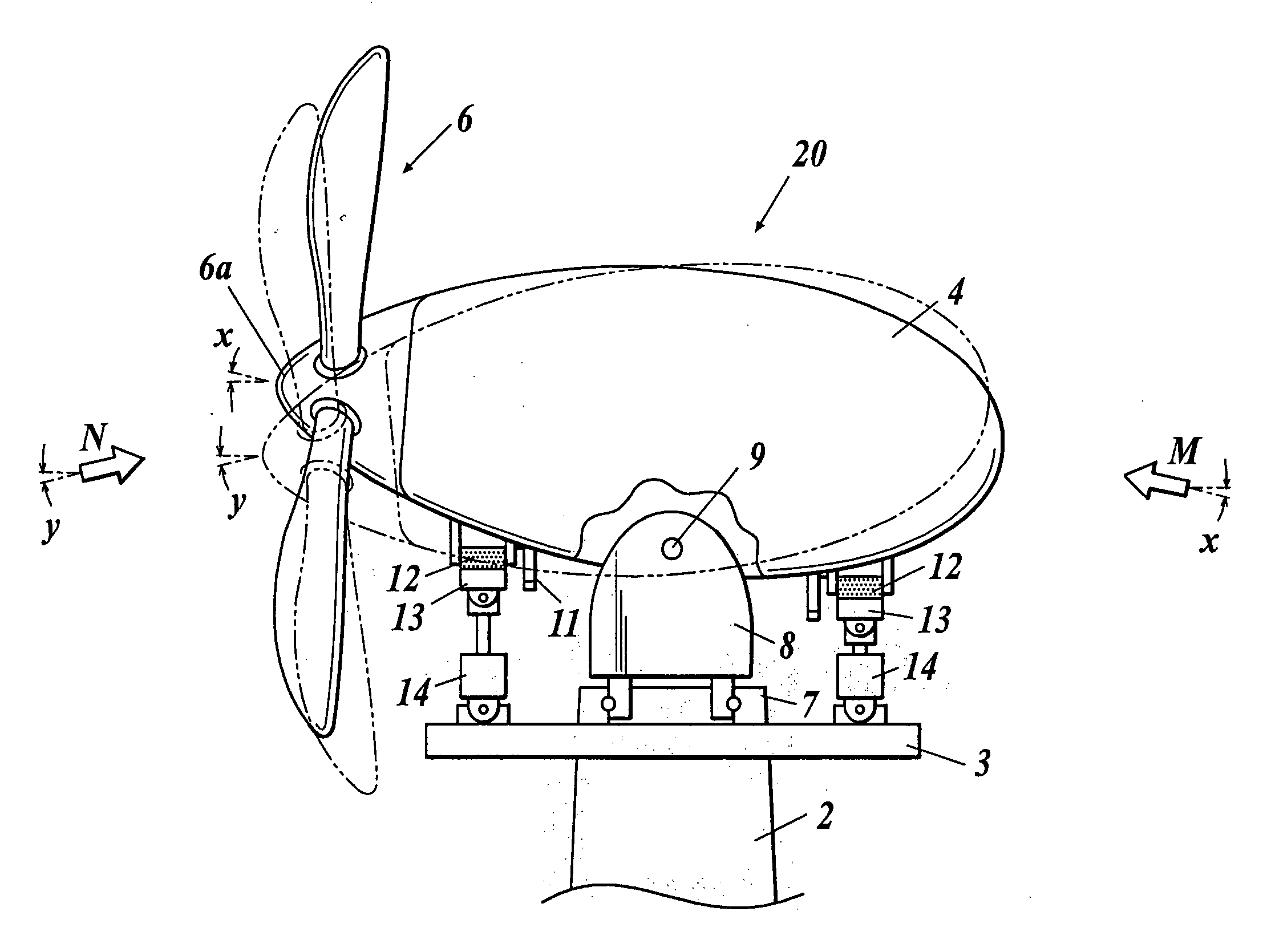
[0034] Next, a horizontal axis wind turbine according to the invention will be explained with reference to FIGS. 3A, 3B and 4. Here, the elements in FIGS. 3A, 3B and 4 which are substantially the same as corresponding elements in FIGS. 1 and 2 are designated by the same reference numerals and the description thereof is omitted.

[0035] A horizontal axis wind turbine 20 is a downwind horizontal axis wind turbine similar to the above-described wind turbine 1. However, the wind turbine 20 can control azimuth angles and tilt angles according to the change of wind direction which is indicated by an arrow in FIG. 3A.

[0036] The horizontal axis wind turbine 20 includes, as shown in FIG. 3A, a tower head pedestal 3 arranged on the above-described tower 2 which is placed on the ground, and a nacelle support member 8 on which the nacelle 4 is disposed to be rotatable about a vertical axis above the pedestal 3 through a bearing 7. The support member 8 supports the nacelle 4 by a pin 9 disposed a...


PUM


Abstract

A horizontal axis wind turbine is disclosed. When a wind direction changes to blow against a rotor from a rear side, a pitch angle of a rotor blade of the rotor are controlled to reverse a rotation of the rotor, without turning of the rotor to the rear side.

Description

CROSS-REFERENCE TO RELATED APPLICATIONS [0001] This application is based upon and claims the benefit of priority from the prior Japanese Patent Application No. 2005-011225, filed on Jan. 19, 2005, and the entire contents of which are incorporated herein by reference. BACKGROUND OF THE INVENTION [0002] 1. Field of the Invention [0003] The present invention relates to a horizontal axis wind turbine, and more particularly to a horizontal axis wind turbine in which a rotating direction of a rotor changes according to a change of the wind direction by, for example, changing pitch angles of rotor blades, and further the direction of the wind turbine can be changed appropriately according to the change of the wind direction at its placed position. [0004] 2. Description of the Related Art [0005] There has been known a horizontal axis wind turbine of downwind type, for example, as shown in FIG. 5, as a conventional example of a horizontal axis wind turbine which performs direction control ac...

Claims


Application Information

Patent Timeline
IPC IPC(8): B63H1/06
CPCF01D1/30F03D1/0608F03D7/02F03D7/0204F03D7/0224F05B2210/404Y02E10/721Y02E10/723F05D2210/44Y02E10/72
Inventor NAGAO, TORU
Owner SUBARU CORP
Why Eureka
Try Eureka