
Frequency converter for a spectral conversion of a start signal and method for a spectral conversion of a start signal

a frequency converter and start signal technology, applied in the field of digital signal processing, can solve the problems of high circuit engineering (or numerics, respectively), high cost of transmitter manufacturing, and high circuit technology costs, so as to reduce the work cycle frequency of the frequency converter, increase efficiency, and cost

Inactive Publication Date: 2006-07-20
FRAUNHOFER GESELLSCHAFT ZUR FOERDERUNG DER ANGEWANDTEN FORSCHUNG EV
View PDF4 Cites 20 Cited by
  • Summary
  • Abstract
  • Description
  • Claims
  • Application Information

AI Technical Summary

Benefits of technology

[0018] It is thus an 
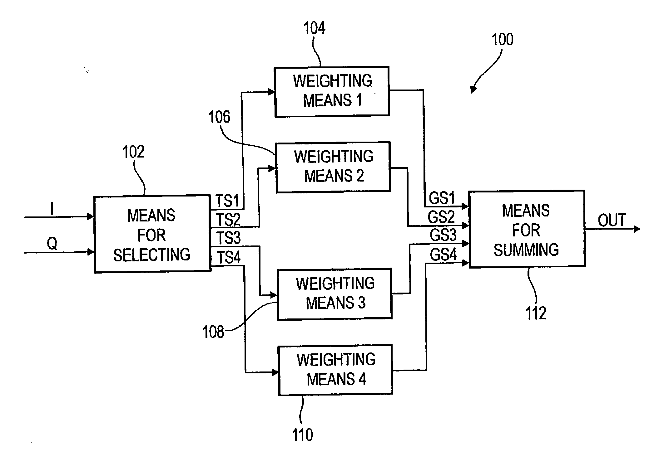
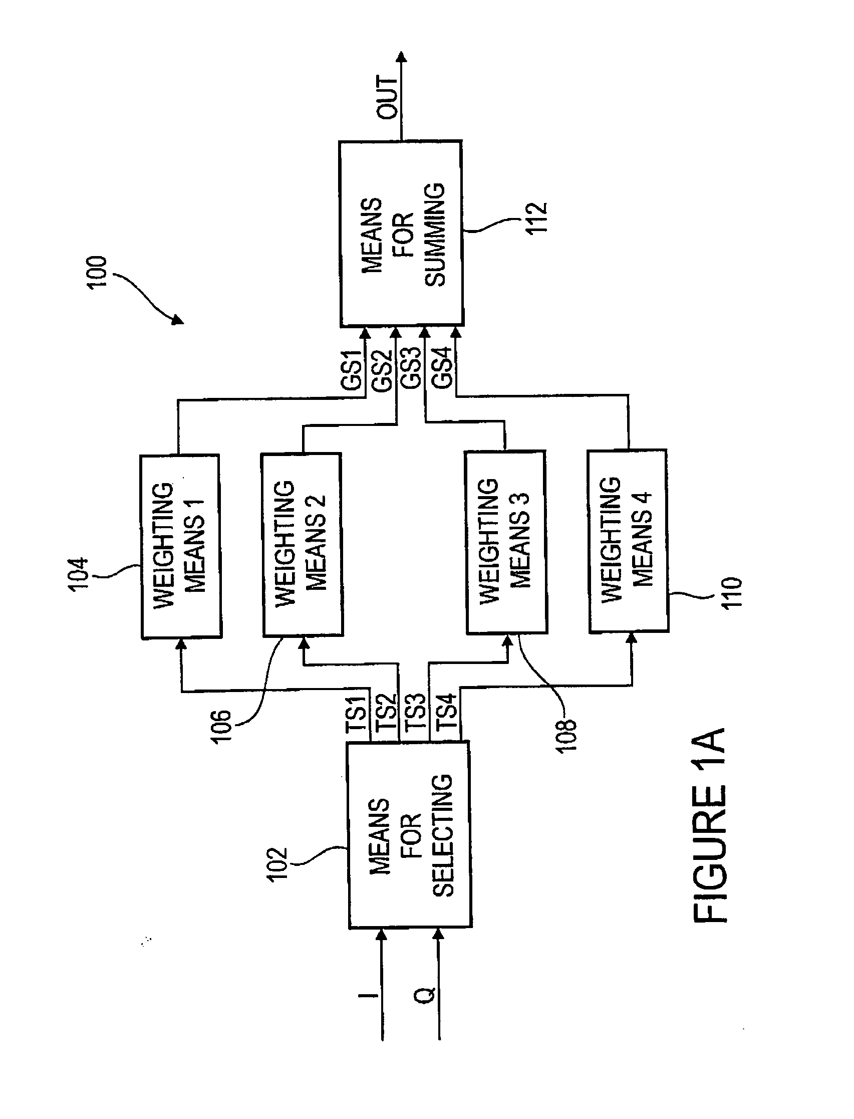
advantage of the present invention that already in means for selecting a split-up of the signal into several sub-signals is performed, wherein preferably the signal is split up into a number of sub-signals corresponding to a downsampling factor. By this, already the basis for a downsampling to be performed using the downsampling factor is provided. Further, means for weighting, for example weighting each of the sub-signals, may be implemented such that it performs a low-pass filtering. The filtering may then be performed in the form of a polyphase filtering with the individual sub-signals as polyphase signals. The advantage of such a low-pass polyphase filtering is that several signal values do not have to be multiplied one after the other by several filter coefficients and be subsequently summed, but that rather by splitting up into individual polyphase signals (i.e. sub-signals) a parallelization of the processing is possible. This further results in a lower work cycle frequency of the frequency converter than would be required in a conventional, serial FIR low-pass filtering. A reduction of the clock frequency further results in an increase of the efficiency with regard to numerics or circuit engineering, whereby a cost reduction and (due to the lower clock frequency) also a lower power consumption of the proposed frequency converter with regard to the conventional frequency converter may be realized. Finally, in means for summing a merging of the individual weighting signals takes place, for example corresponding to the low-pass-filtered polyphase signals (i.e. the low-pass-filtered sub-signals). Such a summation thus corresponds to the summation of individual weighted samples, as it takes place according to the known (serial) FIR filter regulation.
[0019] Further, already in means for selecting, by a suitable selection of I component values or Q component values for the sub-signals, already first steps for the rearrangement of real and imaginary part values of the signal values required from the known mixing method may be performed. If now additionally a negation of corresponding real or imaginary part values, i.e. a negation of values of a sub-signal with regard to the I or Q component values is performed, thus simultaneously the above-described mixer with the frequency conversion of one quarter of the sampling frequency may be realized efficiently. In means for selecting or in means for weighting, still again a negation of real or imaginary part values of the signal may be performed. This means that already by means for selecting (and partially by means for weighting) the mixer function may be formed.
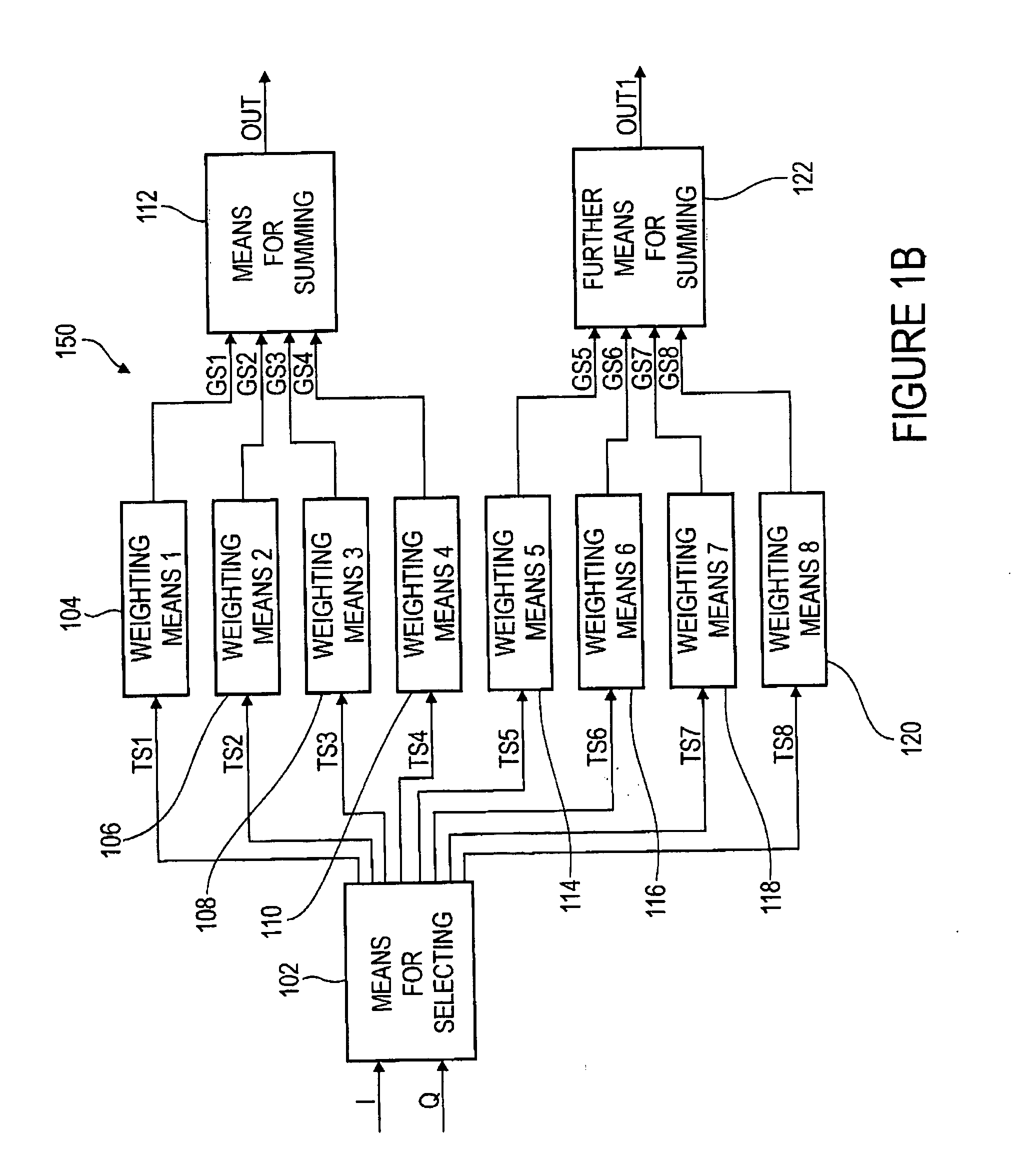
[0020] According to an embodiment of the present invention, means for selecting may be implemented to provide a first, second and fourth auxiliary signal. Here, further, means for weighting may be implemented to weight the first auxiliary signal with one or several weighting coefficients to obtain a fifth weighting signal, to weight the second auxiliary signal with one or several weighting coefficients to obtain a sixth weighting signal, to weight the third auxiliary signal with one or several weighting coefficients to obtain a seventh weighting signal and to weight the fourth auxiliary signal with one or several weighting coefficients to obtain an eighth weighting signal. Preferably, the fifth, sixth, seventh and eighth weighting signal are added in further means for summing, to obtain a further end signal. Preferably, means for selecting may also be implemented to calculate the further end signal based on the first, second, third and fourth auxiliary signal such that it is a complementary signal to the end signal. To this end, means for selecting may in particular be implemented so that each of the first, second, third and fourth auxiliary signals corresponds to a complementary sub-signal of the first, second, third or fourth sub-signals.
[0021] Further, means for weighting may preferably be implemented to weight the first, second, third and fourth auxiliary signal in an analog way, like the first, second, third and fourth sub-signal, to obtain the fifth, sixth, seventh and eighth weighting signal. By adding the fifth, sixth, seventh and eighth weighting signal of means for weighting, thus the further end signal may be provided corresponding to a complementary signal to the end signal by a suitable selection of I or Q component values in means for selecting.
[0022] Such an approach comprising the calculation of the further end signal offers the advantage that already in a parallel calculation of the end signal and the further end signal (complementary signal) a clear acceleration of the determination of a signal rendered for a further processing is possible, wherein the signal rendered for the further processing comprises a component corresponding to the end signal and a component corresponding to the complementary signal. In this case, by a corresponding implementation of means for selecting, further means for weighting and further means for summing, a comparatively low additional overhead as compared to conventional frequency converters is necessary.

Problems solved by technology

In an analog mixer, a high expense in circuit technology is necessary, as for a precise mixing to the target frequency highly accurate mixer members are required which substantially increase the costs of the transmitter to be manufactured.
It is to be noted with regard to a digital mixer that in certain respects a high expense in terms of circuit engineering (or numerics, respectively) is required when the signal is to be mixed onto a freely selectable random target frequency.
The same require, by the use of the Fourier transformation, a partially substantial computational overhead, in particular if only a few of the frequency sub-bands from a large frequency band having several individual frequency sub-bands are required.
Such an approach of a mixer 2402 easy to be realized in numerics or circuit engineering has the disadvantage that by the predetermined connection between the current frequency and the sampling frequency only intermediate frequencies may be obtained which are arranged in a spectral interval of a quarter of the sampling frequency around the current frequency.
This reduces the applicability of such a mixer 2402 which is efficiently realized regarding numerics or circuit engineering.
It is a further disadvantage of a conventional mixer device as it is, for example, characterized by the conventional mixer device 2400 in FIG. 24, that for a spectral conversion, a low-pass filtering and subsequent subsampling two or more individual stages are required.
This leads to a substantial overhead in numerics or circuit engineering, respectively, when realizing such a spectral conversion with a subsequent downsampling as a computer algorithm or as a circuit structure.

Method used


Image

  • Frequency converter for a spectral conversion of a start signal and method for a spectral conversion of a start signal
  • Frequency converter for a spectral conversion of a start signal and method for a spectral conversion of a start signal
  • Frequency converter for a spectral conversion of a start signal and method for a spectral conversion of a start signal

Examples


Embodiment Construction

[0052] In the following description of the preferred embodiments of the present invention, for like elements illustrated in the different drawings like or similar reference numerals are used, wherein a repeated description of those elements is omitted.

[0053]FIG. 1A shows an embodiment of the inventive frequency converter for a spectral conversion of a start signal having a current frequency to an end signal having a target frequency. Here, a frequency converter 100 includes means for selecting 102, first weighting means 104, second weighting means 106, third weighting means 108, fourth weighting means 110 and means for summing 112. Means 102 for selecting includes a first input I for receiving I component values of an I component of the start signal and a second input Q for receiving Q component values of a Q component of the start signal. Further, means 102 for selecting includes a first output for outputting a first sub-signal TS1, a second output for outputting a second sub-sign...


PUM


Abstract

A frequency converter for a spectral conversion of a start signal having a current frequency to an end signal having a target frequency, wherein the start signal includes an I component having a plurality of I component values and a Q component having a plurality of Q component values, comprises means for selecting a plurality of sub-signals based on the I component or the Q component, wherein a sub-signal, depending on a raster, includes selectable I component values, and wherein another sub-signal, depending on the raster, includes selected Q component values. Further, the frequency converter comprises means for weighting each of the plurality of sub-signals, wherein means for weighting is implemented to weight each of the plurality of sub-signals with one weighting factor each to obtain a plurality of weighting signals. Additionally, the frequency converter comprises means for summing the plurality of weighting signals to obtain the end signal having the target frequency. By such a frequency converter and a corresponding method for a spectral conversion, it is possible, in simply realizable way regarding numerics and circuit engineering, to provide a spectral frequency converter to convert a start signal having a current frequency to an end signal having a target frequency.

Description

BACKGROUND OF THE INVENTION [0001] 1. Field of the Invention [0002] The present invention relates to the partial field of digital signal processing, and, in particular, the present invention relates to a frequency converter (mixer), as it is required for a spectral conversion of a signal from one frequency to another frequency. In particular, such a frequency converter may be used in high-frequency technology or in telecommunications. [0003] 2. Description of the Related Art [0004] In telecommunications, to shift a signal from a current frequency (current frequency) into a higher transmission frequency (target frequency) mainly mixers are used. For such a shifting, for example in the transmitter several different possibilities are possible. First, a signal having a low bandwidth Blow may be shifted to different center frequencies within a large bandwidth B. If this center frequency is constant over a longer period of time, then this means nothing but the selection of a subband withi...

Claims


Application Information

Patent Timeline
IPC IPC(8): H04L27/22
CPCH03D7/00H03H17/0273H04L27/2647
Inventor BREILING, MARCO
Owner FRAUNHOFER GESELLSCHAFT ZUR FOERDERUNG DER ANGEWANDTEN FORSCHUNG EV
Learn More