
Converging optical apparatus, optical pickup and optical disc apparatus

Inactive Publication Date: 2006-07-20
SONY CORP
View PDF2 Cites 7 Cited by
  • Summary
  • Abstract
  • Description
  • Claims
  • Application Information

AI Technical Summary

Benefits of technology

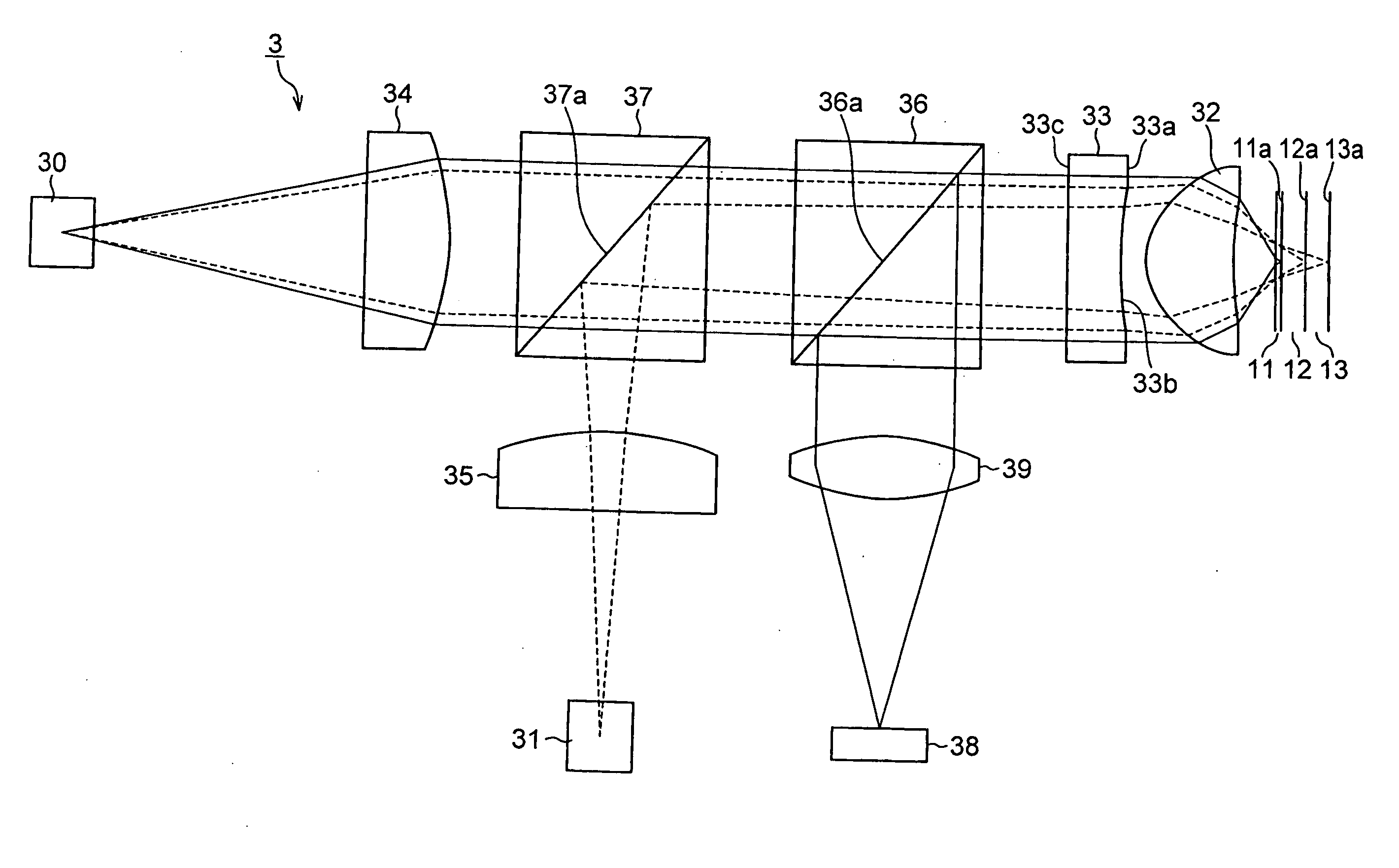
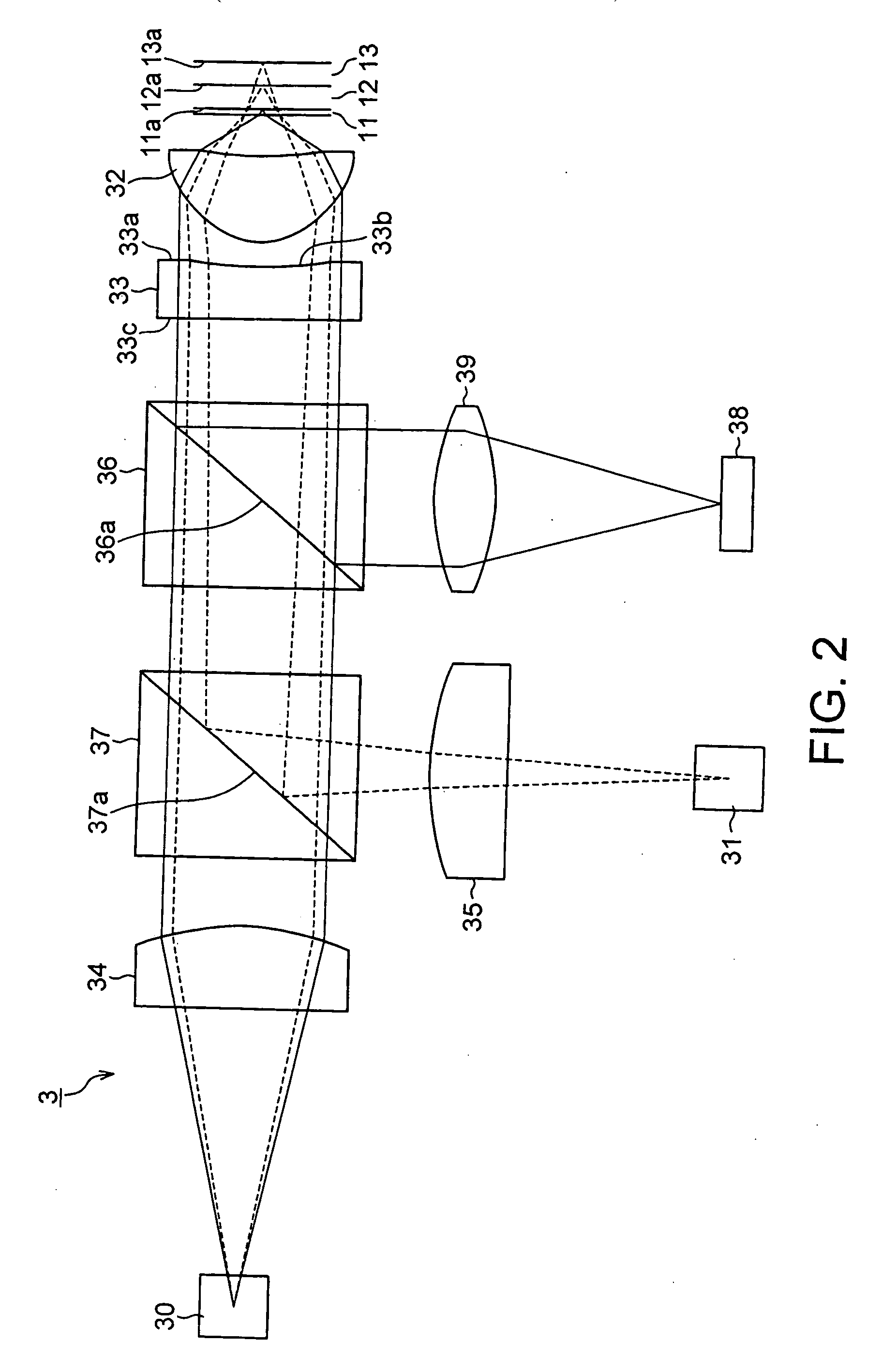
[0014] It is therefore desirable to provide a converging optical apparatus, an optical pickup and an optical disc apparatus that can reduce the diffraction loss due to a hologram element and improve the diffraction efficiency to achieve excellent recording / reproduction performances by realizing compatibility with three different wavelengths by means of a hologram section arranged on only one of the two surfaces of the hologram element.
[0018] Thus, as a converging optical apparatus according to the invention includes a hologram element arranged between a light source section and an objective lens for converging light beams emitted from the light source section of three different respective wavelengths, and the hologram element is provided with a reference curved surface on one of the major surfaces thereof, the reference curved surface being an aspherical shape, and a hologram section is formed on the reference curved surface, it is now possible to realize compatibility with three different wavelengths and reduce the diffraction loss due to the hologram element in order to prevent the fall of the quantity of light of the light beam being converged on an optical disc. Thus, it is now possible to achieve excellent recording and reproduction performances.

Problems solved by technology

Such an arrangement baffles efforts for downsizing the apparatus and makes the entire structure a very complex one.
While an optical pickup having such a diffraction element and an objective lens can correct the aberration attributable to the thickness of disc by means of the diffraction element, there can arise a problem of a reduced quantity of light due to the diffraction efficiency at both surfaces of the diffraction element.
Thus, it has been very difficult to realize an optical pickup compatible with high density recording optical discs, DVDs and CDs that use different wavelengths and capable of achieving excellent recording / reproduction performances relative to optical discs because of various problems including the problem of a reduced quantity of light due to diffraction losses.

Method used


Image

  • Converging optical apparatus, optical pickup and optical disc apparatus
  • Converging optical apparatus, optical pickup and optical disc apparatus
  • Converging optical apparatus, optical pickup and optical disc apparatus

Examples


example

[0156] Now, the hologram element 33 and the objective lens 32 of an optical pickup according to the invention will be described more specifically by referring to FIGS. 7 and 8 and the numerical data listed in Tables 1 through 3 shown below.

TABLE 1hologram coefficientC1−1.7147E−02C2 2.4681E−03C3 8.7169E−03C4−5.7344E−03C5 2.3280E−03

[0157]

TABLE 2aspherical coefficientc 0.131k−1.0A−9.4077E−03B−3.3226E−03C 2.1858E−02D−8.8737E−03

[0158]

TABLE 3S1S2r 1.33737 6.48654k−0.38627−16.5297A−3.5645E−03−4.6689E−02B 2.6174E−03 3.5462E−01C−1.1319E−02−1.1835E+00D 1.9685E−02 1.6808E+00E−1.6661E−02−5.7116E−01F 3.1738E−03−1.2688E+00G 2.6161E−03 1.7314E+00H−1.4267E−03−8.6942E−01J 1.9881E−04 1.6234E−01

[0159] Table 1 above shows specific values selected for the hologram coefficients of the hologram section 33b of the hologram element 33 in the formula (4) cited above. Table 2 shows specific values selected for the aspherical coefficients of the aspherical shape of the reference curved surface of the hologra...


PUM


Abstract

A converging optical apparatus reduces the diffraction loss and realizes compatibility with three different wavelengths by means of a hologram element. The present invention provides an optical pickup for recording signals on and / or reproducing signals from a plurality of optical discs having respective protection substrates of different thicknesses for protecting the recording surfaces thereof by means of light beams of different wavelengths, the optical pickup including a first emission section that emits a light beam of a first wavelength, a second emission section that emits a light beam of a second wavelength, a third emission section that emits a light beam of a third wavelength, an objective lens for converging the light beams of the first through third wavelengths emitted respectively from the first through third emission sections on the signal recording surfaces of the optical discs, and a hologram element arranged between the first through third emission sections and the objective lens, the hologram element having two major surfaces, wherein the hologram element is provided with a reference curved surface on one of the major surfaces thereof, the reference curved surface being an aspherical shape, and a hologram section is formed on the reference curved surface.

Description

CROSS REFERENCES TO RELATED APPLICATIONS [0001] The present invention contains subject matter related to Japanese Patent Application JP 2004-381517 filed in the Japanese Patent Office on Dec. 28, 2004, and Japanese Patent Application JP 2005-067819 filed in the Japanese Patent Office on Mar. 10, 2005, the entire contents of which being incorporated by reference. BACKGROUND OF THE INVENTION [0002] 1. Field of the Invention [0003] This invention relates to a converging optical apparatus and an optical pickup that can record information signals on and reproduce information signals from a disc-shaped recording medium of any of three different types by means of a single objective lens and also to an optical disc apparatus using the same. [0004] 2. Description of the Related Art [0005] Optical discs adapted to high density recording and reproduction of signals by means of a light beam with a wavelength of about 405 nm emitted from a blue-purple semiconductor laser (to be referred to as hi...

Claims


Application Information

Patent Timeline
IPC IPC(8): G11B7/00
CPCG11B7/1275G11B7/1353G11B7/1356G11B7/1374G11B7/13922G11B2007/0006
Inventor HINENO, SATOSHI
Owner SONY CORP
Learn More