Liquefied natural gas floating storage regasification unit

Inactive Publication Date: 2006-07-20
SHELL OIL CO
View PDF96 Cites 116 Cited by
  • Summary
  • Abstract
  • Description
  • Claims
  • Application Information

AI Technical Summary

Benefits of technology

[0012] In some embodiments, an FSRU of the invention may comprise a second mooring system that provides for a mooring or docking of an LNG carrier to the FSRU. The second mooring system may comprise docking equipment on the FSRU. The second mooring system may comprise docking equipment disposed on an upper surface of the FSRU. The docking equipment may be configured to couple an LNG carrier to the FSRU. The FSRU may also provide some protection from waves while the LNG carrier is docked alongside the FSRU.
[0013] Mooring of an LNG carrier with the LNG FSRU may be accomplished using mooring lines. In an embodiment, docking equipment may be placed at a different elevation than the other LNG processing equipment. The docking equipment may be placed at an elevation to minimize the angles on mooring lines between the docking equipment and a docked LNG carrier. By placing and / or modifying the unit to have different elevations for the docking equipment and the other LNG processing equipment, the FSRU may accommodate LNG carriers directly alongside the FSRU. Additionally, fenders may be placed at various positions about the FSRU to protect the FSRU from collisions with LNG carriers. In one embodiment, fenders may be placed along a docking side of the FSRU and at corners of the FSRU. Example fenders that may be used for the mooring arrangement may be of the Yokohama (pneumatic) type with a diameter in a range of from about 4.5 meters to about 9 meters in length.
[0014] A system of ballast storage areas, also referred to as ballast cells or tanks, may be disposed throughout the FSRU. In some embodiments, liquid ballast (e.g., water), may be used to fill the ballast storage areas. The system of ballast storage areas may provide for stability and for control of draft of the FSRU during loading and unloading of LNG.

Problems solved by technology

The inherent dangers of handling LNG make such on-shore facilities less desirable to inhabitants who live near the facilities.

Method used


Image

  • Liquefied natural gas floating storage regasification unit
  • Liquefied natural gas floating storage regasification unit
  • Liquefied natural gas floating storage regasification unit

Examples


Embodiment Construction

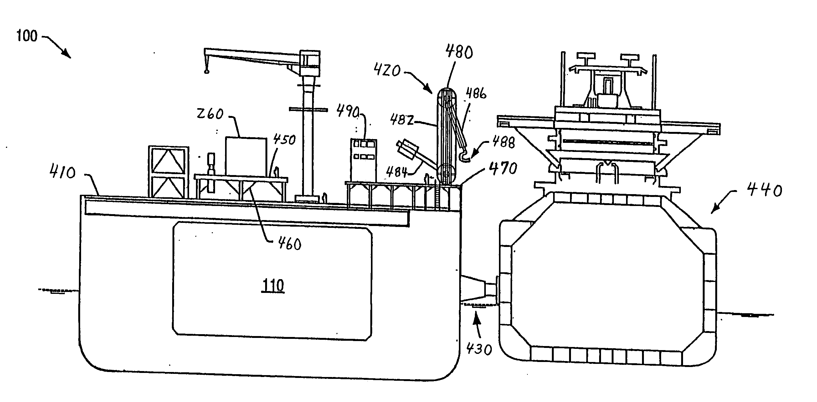
[0028] An offshore liquefied natural gas (“LNG”) floating storage regasification unit (“FSRU”), also referred to as unit (“unit”), of the invention may allow LNG carriers to berth directly alongside the FSRU and unload LNG. The FSRU may include one or more tanks capable of storing LNG. The FSRU may transfer LNG from the tanks to an LNG vaporization plant disposed on the FSRU. The vaporized LNG may then be distributed among one or more natural gas pipelines.

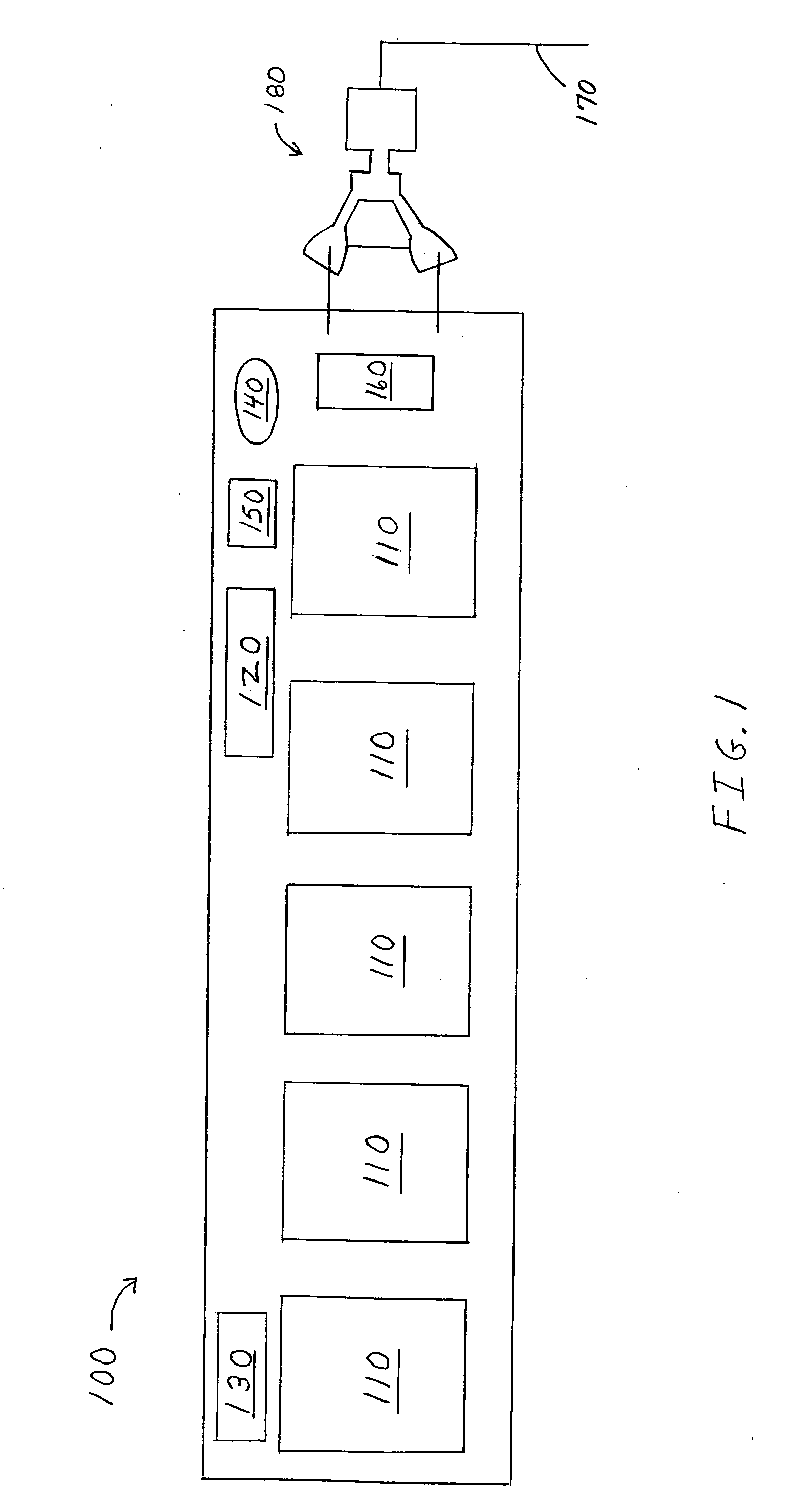
[0029]FIG. 1 depicts an embodiment of an FSRU of the invention. An FSRU 100 may have a layout that includes LNG tanks 110. The tanks may be, for example, cylindrical, square, rectangular, partially spherical, irregularly shaped, and combinations thereof. The FSRU may comprise vaporization process equipment 120 and utilities, docking equipment, living quarters 130, flares 140, vents 150, metering equipment 160, a pipeline 170 for exporting natural gas, and a first mooring system comprising a yoke mooring system 180 for mooring the...


PUM


Abstract

An offshore liquefied natural gas floating storage regasification unit that may receive, store, and process liquefied natural gas from carriers. A floating storage regasification unit may include transfer equipment to offload liquefied natural gas from a carrier, a first mooring system to provide for mooring of a floating storage regasification unit at a location in a body of water, a second mooring system to provide for mooring a carrier to the floating storage regasification unit, and combinations thereof. A portion of the floating storage regasification unit may be composed of a double-hull containment structure.

Description

CROSS-REFERENCE TO RELATED APPLICATIONS [0001] This application claims the benefit of U.S. Provisional Application No. 60 / 626,041, filed Nov. , 2004 which is incorporated herein by reference.BACKGROUND OF THE INVENTION [0002] 1. Field of Invention [0003] The invention generally relates to structures configured to store liquefied natural gas and distribute natural gas. More specifically the invention relates to liquefied natural gas processing. [0004] 2. Description of Related Art [0005] Natural gas is becoming a fuel of choice for power generation in the U.S. and other countries. Natural gas is an efficient fuel source that produces lower pollutant emissions than many other fuel sources. Additionally, gains in efficiency of power generation using natural gas and the relatively low initial investment costs of building natural gas based power generation facilities, make natural gas an attractive alternative to other fuels. [0006] Distribution and storage of an adequate supply of natur...

Claims


Application Information

Patent Timeline
IPC IPC(8): F17C9/02F17C13/08
CPCB63B25/16B63B35/44B63B38/00F17C5/06F17C7/04F17C9/02F17C2201/052F17C2205/0107F17C2205/0126F17C2205/0157F17C2221/033F17C2221/035F17C2223/0153F17C2223/0161F17C2223/033F17C2225/0123F17C2225/035F17C2227/0393F17C2265/05F17C2270/0102F17C2270/0105F17C2270/0113F17C2270/0126B63B35/00
Inventor CUSITER, JAMES MILNECARPENTER, DAVID GEORGE MICHAELSPAARMAN, RENESTEPHENS, ANDREW NEILBOWRING, STEVEN JAMESOTTEN, EVELINE IRISMEEK, HARKE JAN
Owner SHELL OIL CO
Why Eureka
Try Eureka