
Rotary type electric shaver

a rotary type, electric shaver technology, applied in the direction of metal working devices, etc., can solve the problems of insufficient shaving depth, inability to cut hair deep enough, poor shaving performance, etc., to prevent over-deep shaving, reduce shaving difficulty, and reduce shaving difficulty

Inactive Publication Date: 2006-07-20
IZUMI PROD CO
View PDF61 Cites 4 Cited by
  • Summary
  • Abstract
  • Description
  • Claims
  • Application Information

AI Technical Summary

Benefits of technology

[0012] The object of the present invention is to provide a rotary type electric shaver in which an excellent shaving feeling is obtainable even when the outer cutter is used while being lightly pressed against the skin, the sliding surface (cutting surface) where the cutter blades of the inner cutter make a sliding contact with the inner surface of the outer cutter can be polished easily and efficiently by whetstone, and the durability of whetstone is greatly increased.
[0020] In this state, hair enters into the hair introduction opening (slit) of the higher (thicker) portion of the outer cutter, and some hair that has entered is cut here; and when the outer cutter (or the shaver) is moved from this state while touching the skin surface, the hair entered into the hair introduction opening of the thicker portion of the outer cutter is introduced to the lower (or thinner) portion of the outer cutter. Therefore, the remaining hair not cut by the thicker portion of the outer cutter is shaved with sufficient depth. During this process, hair is smoothly introduced from the hair introduction opening of the thicker portion of the outer cutter to the hair introduction opening of the thinner portion; accordingly, it is not necessary to firmly press the outer cutter onto the skin, and it is possible to cut the hair smoothly and with appropriate shaving depth simply by lightly touching the outer cutter to the skin and moving around the shaver.
[0021] Furthermore, the sliding surface where the cutter blades of the inner cutter make a sliding contact with the inner cutter running track of the outer cutter is positioned on a plane (or flat surface) that is perpendicular to the center axis line; accordingly, grinding of the cutting surfaces of the inner cutter running tracks and cutter blades of the inner cutter can be done easily. In other words, since the cutter blades of the inner cutter and the inner cutter running track of the outer cutter are not curved, grinding can be done with a whetstone that has a planar grinding face, and repairing (reviving) the grinding face of the whetstone can be done easily.
[0022] In the present invention, the vertical cross-sectional shape of the top portion of the outer cutter (in cross section on an imaginary radial plane that includes the center axis line that is the rotational center of the inner cutter) is made constant (or can be the same) for the entire circumference, and it can be vary in the circumferential direction. For example, the top portion of the outer cutter can be formed so that only the ring-shaped groove side (or the portions near or alongside the ring-shaped groove) where overly deep shaving is likely to occur is made thinner (or thicker) than the circumferential portions so as to prevent overly deep shaving.
[0023] Furthermore, in the present invention, the outer cutter of a cutter unit can be formed so that a part of the top portion thereof in the circumferential direction is thin on the ring-shaped groove side (or thin near or alongside the ring-shaped groove) with the other part of the top portion being thick. For example, by way of forming the outer circumferential edge of the top portion of the outer cutter where wrinkles in the skin are likely to occur thicker than the other portions, it is possible to prevent overly deep shaving from occurring at such thick circumferential edge.
[0024] For example, in an outer cutter housing that has a plurality of cutter units, the thickness of the top portion of the outer cutter is thin at the ring-shaped groove side (or near or alongside the ring-shaped groove) on the outer circumferential side of the outer cutter housing where the outer cutter is likely to be firmly pressed against skin, and the thickness is made large (or thick) on the center side of the outer cutter housing where the outer cutter is likely to come into contact with the skin perpendicularly. In a shaver with three cutter units installed in a triangular shape, the same effect as describe above is obtained by making the thickness of the areas of the top portions of the outer cutters located outside a triangle formed by connecting the centers of each cutter unit (or the outer cutters) small (thinner) on the ring-shaped groove side (or near or alongside the ring-shaped groove). The areas located inside the triangle, the thickness of the outer cutter top portion can be large at the ring-shaped groove side, or the top portions in such areas can be made flat with no thick or thin portions.

Problems solved by technology

In electric rotary shaves, when, during shaving, plural slit-shaped hair introduction openings (or “slits”) of the outer cutter of a shaver is firmly pressed against skin, the skin would enter into the slits and be cut by the inner cutter (occasionally cut too deeply), causing a burning feeling in the skin after finishing the shaving.
However, increase of the thickness of the outer cutter results in expansion of the distance between the skin and the inner cutter, causing another problem that it is not possible to cut hair deep enough.
In an actual use, however, the outer cutter (or the shaver) is often moved around while touching the skin lightly; and in this case, large wrinkles would not occur on the outer peripheral edge of the outer cutter, and the shaving performance tends to be poor.
Accordingly, the problem is that manufacturing of the outer cutter is not easy, and the productivity is poor.
Furthermore, the whetstone that grinds the sliding surface (cutting surface) that has an outwardly convex shape must be processed in advance so that the whetstone has a grinding surface that matches the curvature of the curved sliding surface; as a result, the durability of the whetstone also becomes an issue.

Method used


Image

  • Rotary type electric shaver
  • Rotary type electric shaver
  • Rotary type electric shaver

Examples


Embodiment Construction

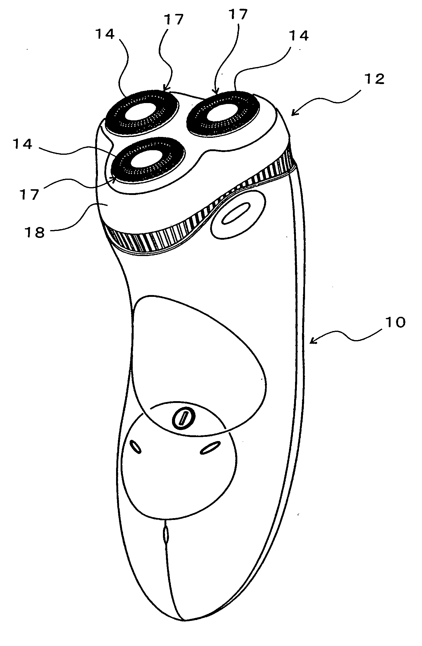
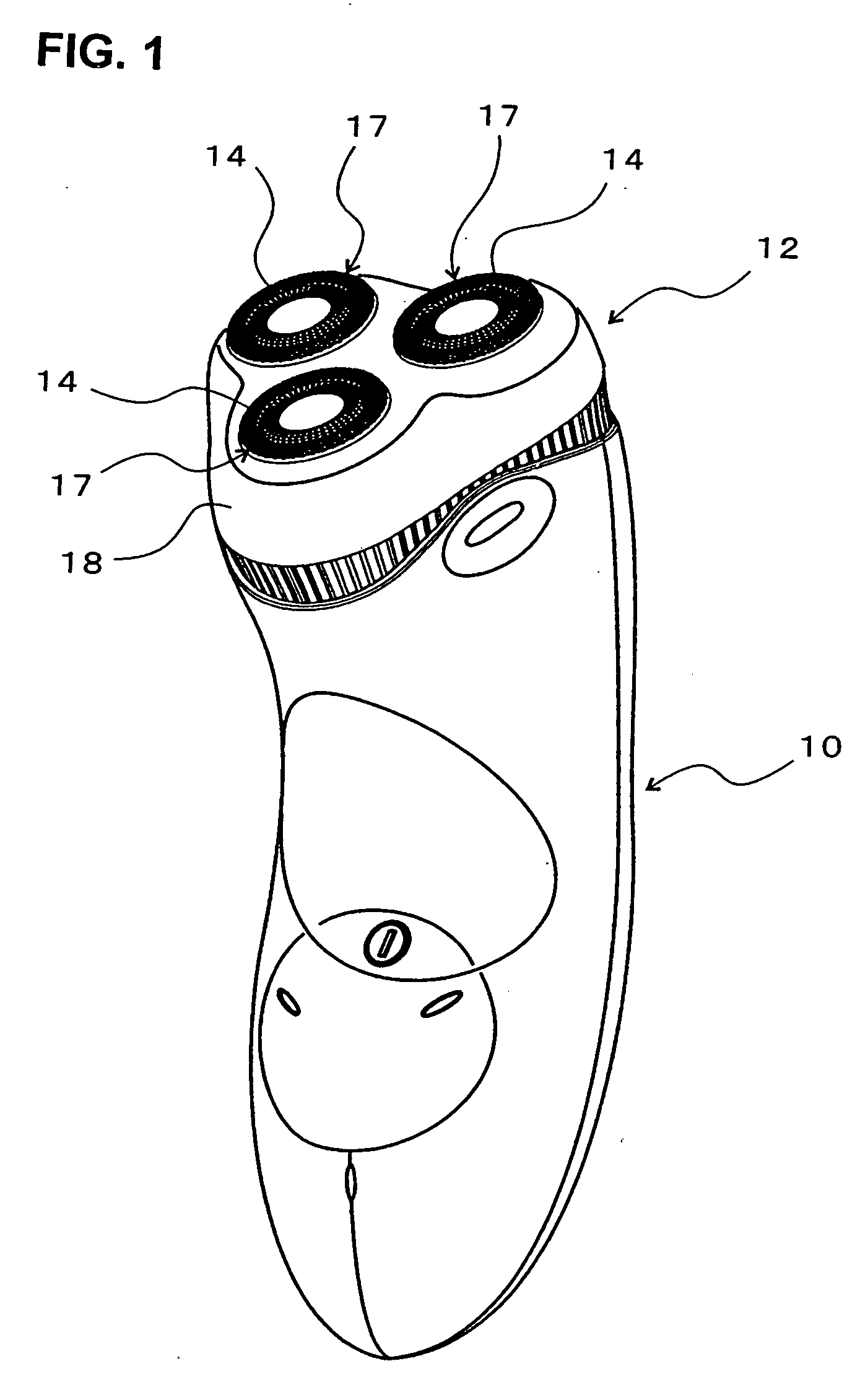
[0032] In FIG. 1, the reference numeral 10 is a shaver main body, and 12 is a cutter head openably or detachably mounted on the shaver main body 10. Three cutter units 17 each comprising an outer cutter 14 and an inner cutter 16 (see FIG. 3) are provided in the cutter head 12. The outer cutters 14 of the three cutter units 17 are positioned with their centers at the vertices of an equilateral triangle.

[0033] The cutter head 12 includes an outer cutter housing 18 that is openable or detachable upward relative to the shaver main body 10, and the outer cutters 14 are installed in three outer cutter installation holes formed in the outer cutter housing 18. Each cutter unit 17 that includes the outer cutter 14 is upwardly urged; in other words, it is urged in the direction that the outer cutter 14 projects upward in FIG. 1.

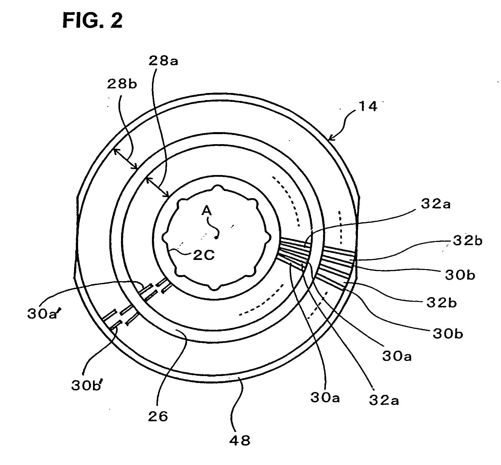
[0034] As seen from FIGS. 2 and 3, the outer cutter 14, which is made of metal, is in substantially a shallow bowl shape. The top portion of the outer cutter 14 is c...


PUM


Abstract

Electric rotary shaver including an outer cutter 14, in which a ring-shaped groove 26 is formed in the top portion and two ring-shaped inner cutter running tracks 34 are formed in the interior surface, and an inner cutter 16, in which a plurality of cutter blades 40 are provided that make sliding contact with the inner cutter running tracks 34 of the outer cutter 14. A sliding surface where the cutter blades of the inner cutter make a sliding contact with the inner cutter running track of the outer cutter is set on a plane C perpendicular to the center axis line (A), and the thickness of the top portion of the outer cutter 14 is such that the portions near the ring-shaped groove 26 are made thinner or thicker than the other part of the top portion on at least a part of the circumference.

Description

BACKGROUND OF THE INVENTION [0001] 1. Technical Field [0002] The present invention relates to a rotary type electric shaver in which an inner cutter(s) rotates while making a sliding contact with an interior surface of an outer cutter(s), so that whiskers (or hair) that advance into hair introduction openings extending in substantially a radial direction in the top portion of the outer cutter is cut by the inner cutter(s). [0003] 2. Description of the Related Art [0004] In electric rotary shaves, when, during shaving, plural slit-shaped hair introduction openings (or “slits”) of the outer cutter of a shaver is firmly pressed against skin, the skin would enter into the slits and be cut by the inner cutter (occasionally cut too deeply), causing a burning feeling in the skin after finishing the shaving. This sort of problem can be prevented by using outer cutters which are made thick. Here, making the outer cutter thick means to increase the dimension of the thickness of the ribs that ...

Claims


Application Information

Patent Timeline
IPC IPC(8): B26B19/14
CPCB26B19/141B26B19/143
Inventor SHIMIZU, TETSUHIKO
Owner IZUMI PROD CO
Learn More