Fuel cell separator and fabrication method thereof, and conductive corrosion-resistant metallic material
a technology of fuel cell separator and fabrication method, which is applied in the direction of cell components, final product manufacturing, sustainable manufacturing/processing, etc., can solve the problems of insufficient corrosion resistance, insufficient prior-art separators to meet the requirements of a lighter separator, and complicated metal materials used now. , to achieve the effect of excellent corrosion resistance and conductivity, good processability, and reduced weigh
Inactive Publication Date: 2006-07-13
HITACHI CABLE
View PDF7 Cites 12 Cited by
- Summary
- Abstract
- Description
- Claims
- Application Information
AI Technical Summary
Benefits of technology
[0041] According to the present invention, it is possible to provide a fuel cell separator, which has excellent corrosion resistance and conductivity, can be reduced in weight, and has good processability, even in a fuel cel
Problems solved by technology
Accordingly, as its raw material, a graphite-based material was used mainly, but a metallic material that has complicated and high-precision processability is used now.
However, the prior-art separators are not adequate to meet the requirements for a lighter separator.
To reduce the weight of separators, although excellent-conductivity and light metals such as Al, Mg, etc. or its alloys have been used as core materials, these materials are insufficient in corrosion resistance so that they tend to dissolve (corrode) under severe conditions such as cell environments, which causes difficulty in direct use thereof.
Here, if pure Al or a low-concentration Al alloy (that has a low concentration of alloy constituents except Al) is used as a core material and Ti is selected as a corrosion-resistant covering material to be brought into direct contact therewith, there is the problem that Ti/Al cladding is extremely difficult to conduct beca
Method used
View moreImage
Smart ImageViewing Examples

Examples
 PUM
| Property | Measurement | Unit |
|---|---|---|
| Fraction | aaaaa | aaaaa |
| Fraction | aaaaa | aaaaa |
| Thickness | aaaaa | aaaaa |
Abstract
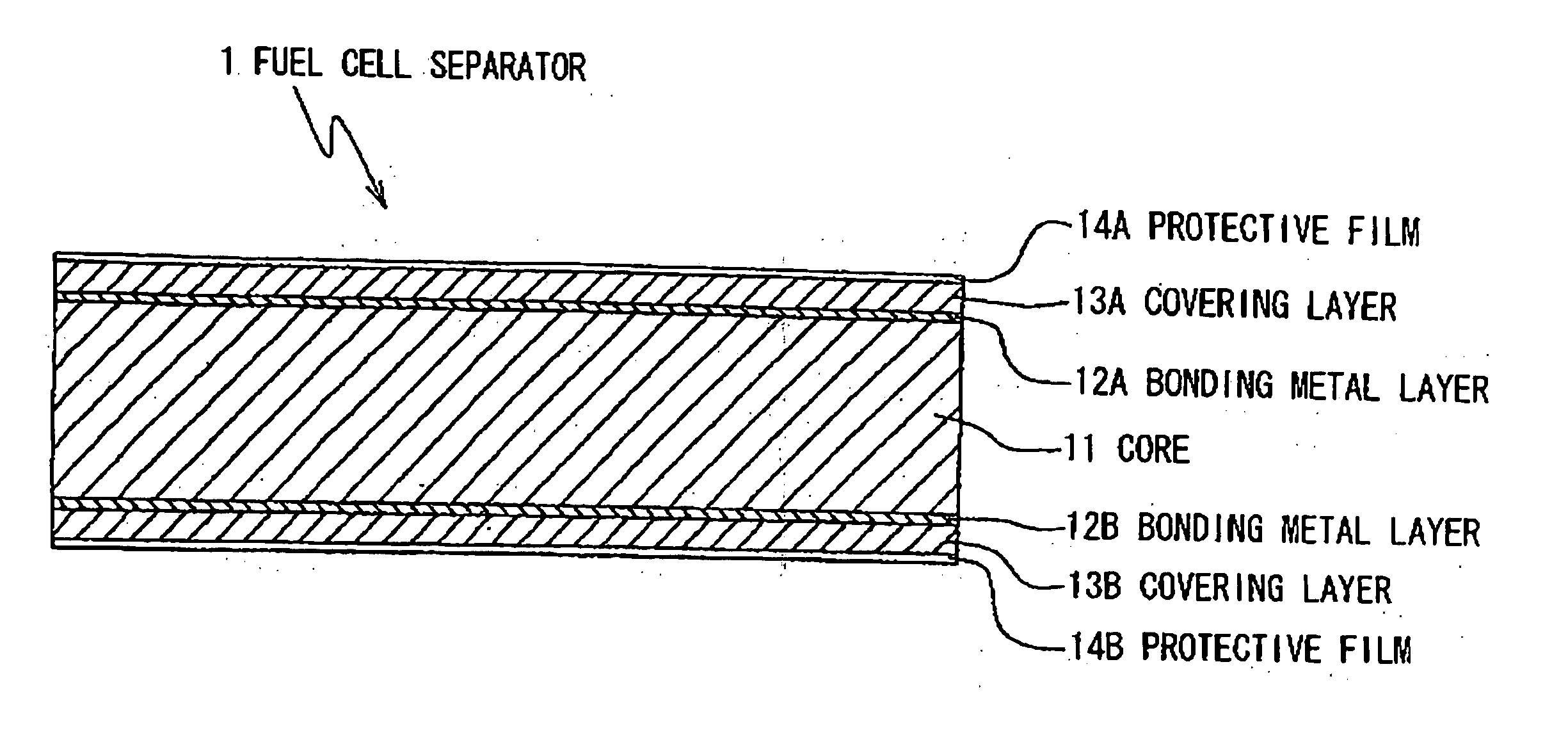
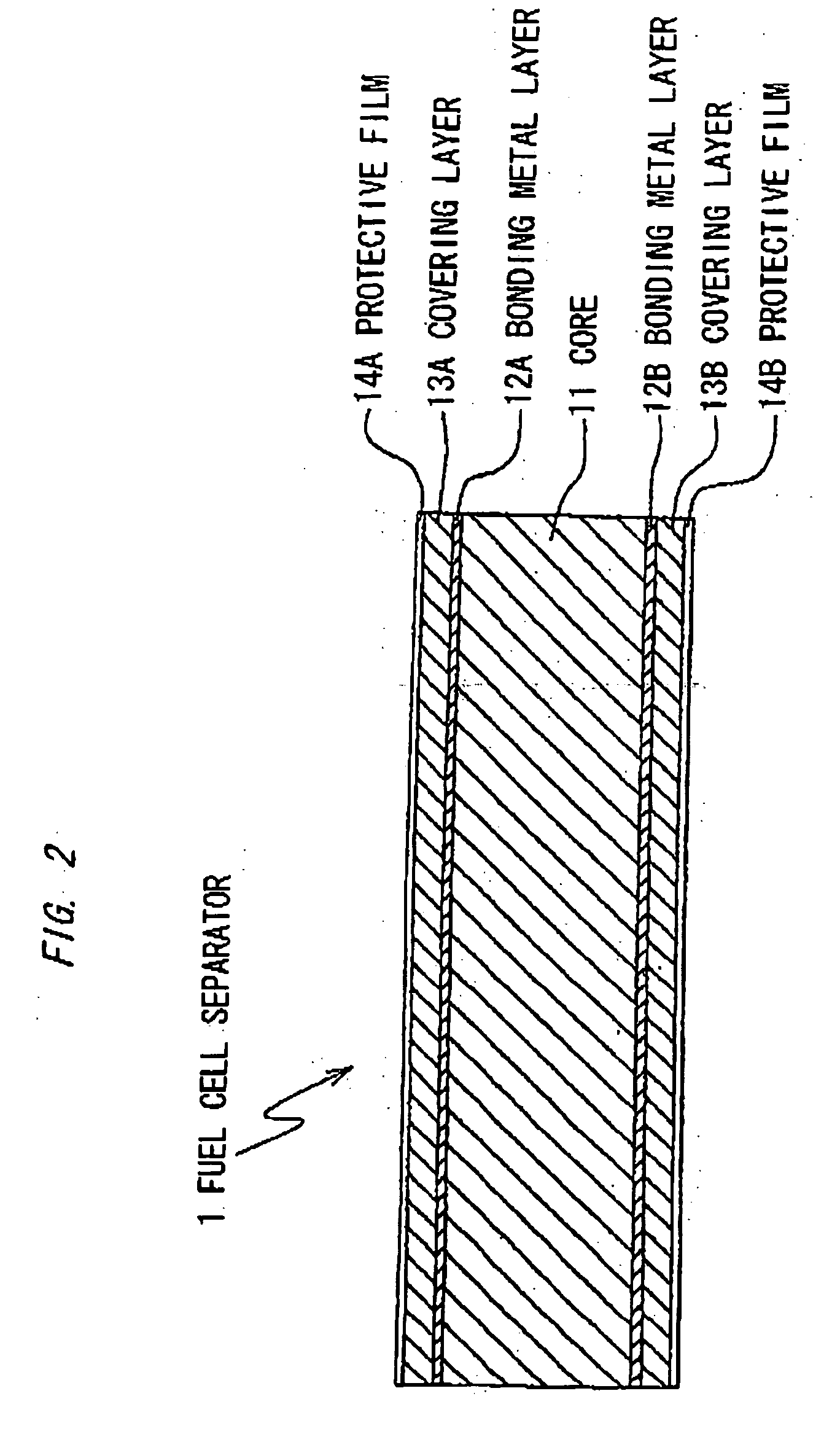
A fuel cell separator is provided with: a core made of an Al alloy or a Mg alloy; a covering layer made of Ti or a Ti alloy formed on at least one side of the core; and a bonding metal layer formed between the core and the covering layer. The bonding metal layer is made of a metal with a deformation resistance lower than the core and the covering layer.
Description
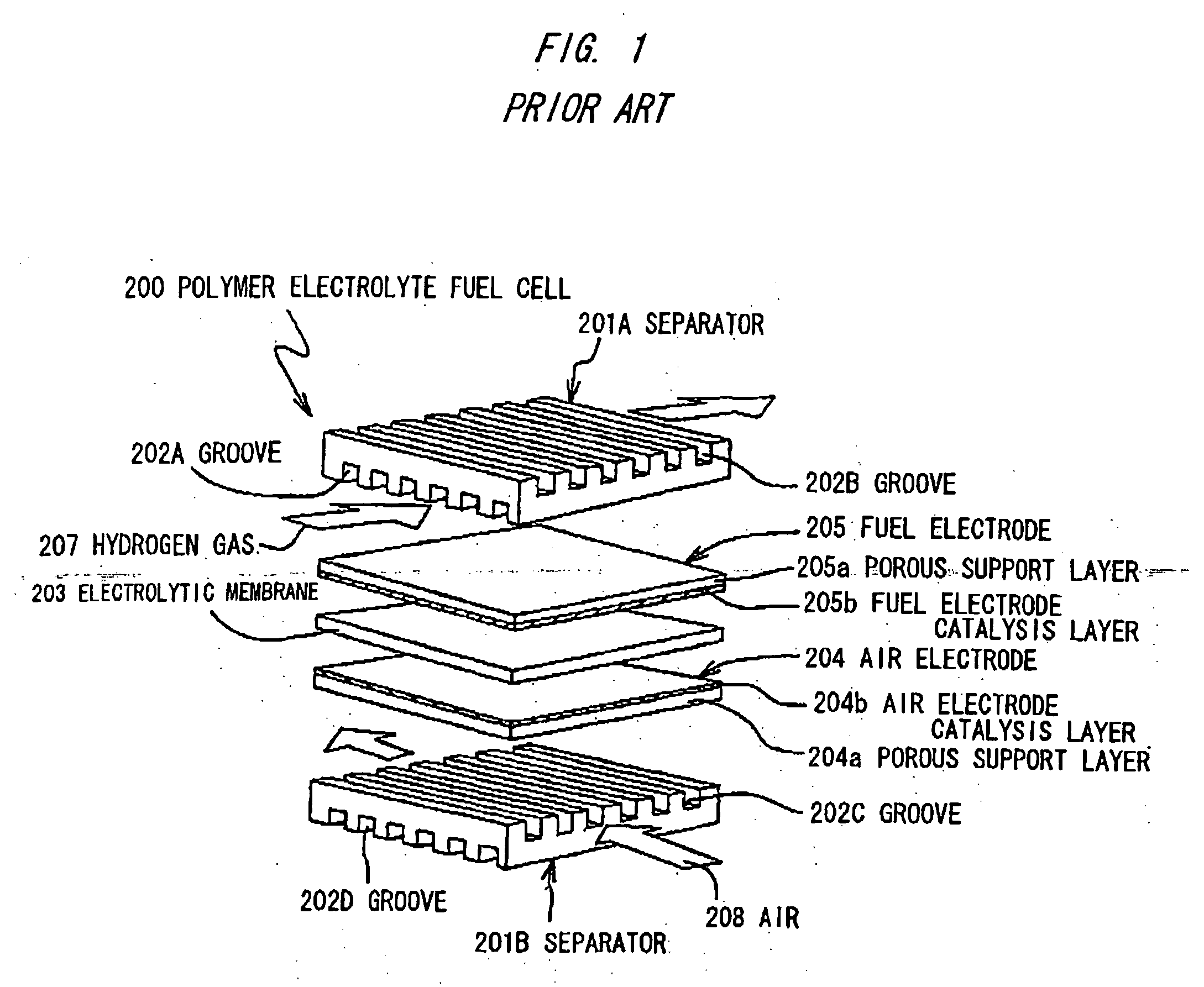
[0001] The present application is based on Japanese patent application Nos. 2004-381883 and 2005-308956, the entire contents of which are incorporated herein by reference. BACKGROUND OF THE INVENTION [0002] 1. Field of the Invention [0003] This invention relates to a fuel cell separator and a fabrication method thereof, and a conductive corrosion-resistant metallic material. In particular, this invention relates to a fuel cell separator having excellent corrosion resistance and conductivity, and good secondary processability even in a fuel cell environment under electrochemically severe conditions, and a fabrication method of the fuel cell separator, and a conductive corrosion-resistant metallic material. [0004] 2. Description of the Related Art [0005] Fuel cells are not only high-efficient because they are capable of directly transforming a chemical change into electrical energy, but are also global environment-friendly because of small amounts of air pollutants (NOx, SOx, etc.) to...
Claims
Login to View More Application Information
Patent Timeline
 IPC IPC(8): H01M8/02B32B15/01B32B15/00
CPCB32B15/017C22C14/00C22C21/00C22C21/08C22C21/12C22C23/02Y10T428/12736H01M8/0213H01M8/0215H01M8/0228Y02E60/50Y10T428/12729H01M8/0208Y02P70/50
Inventor SEIDO, MASAHIROWASHIMA, MINEONAKAGAWA, KAZUHIKOFUKUDA, KUNIHIROSASAOKA, TAKAAKINOMURA, KATSUMI
Owner HITACHI CABLE
Features
- R&D
- Intellectual Property
- Life Sciences
- Materials
- Tech Scout
- Unparalleled Data Quality
- Higher Quality Content
- 60% Fewer Hallucinations
Learn More Browse by: Latest US Patents, China's latest patents, Technical Efficacy Thesaurus, Application Domain, Technology Topic, Popular Technical Reports.
© 2025 PatSnap. All rights reserved.Legal|Privacy policy|Modern Slavery Act Transparency Statement|Sitemap|About US| Contact US: help@patsnap.com