Exhaust gas aftertreatment installation and method
- Summary
- Abstract
- Description
- Claims
- Application Information
AI Technical Summary
Benefits of technology
Problems solved by technology
Method used
Image
Examples
Example
DETAILED DESCRIPTION OF THE DRAWINGS
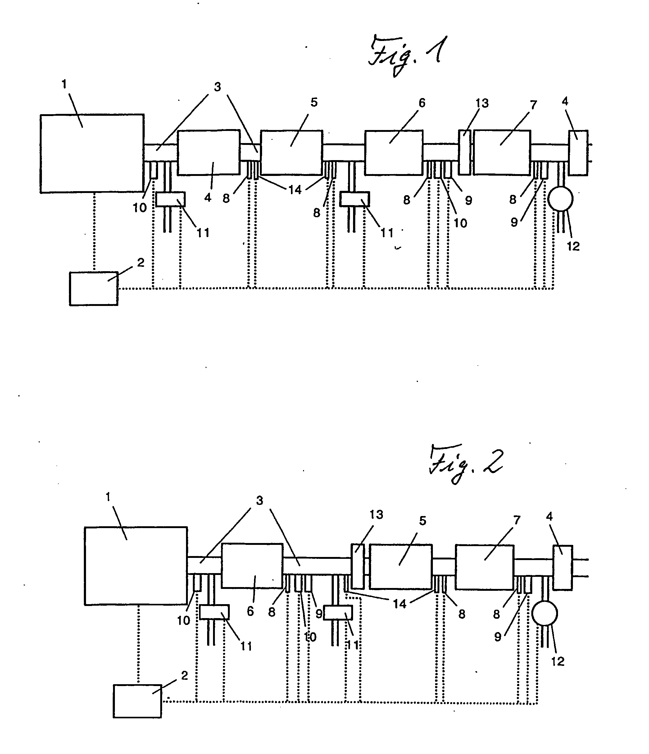
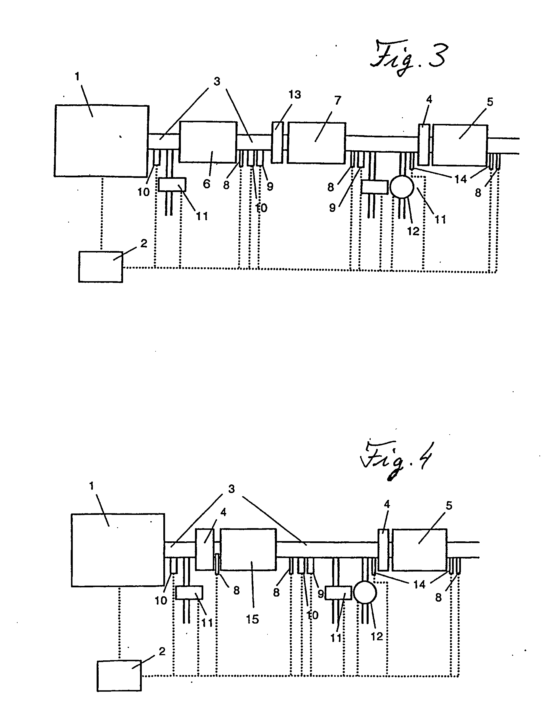
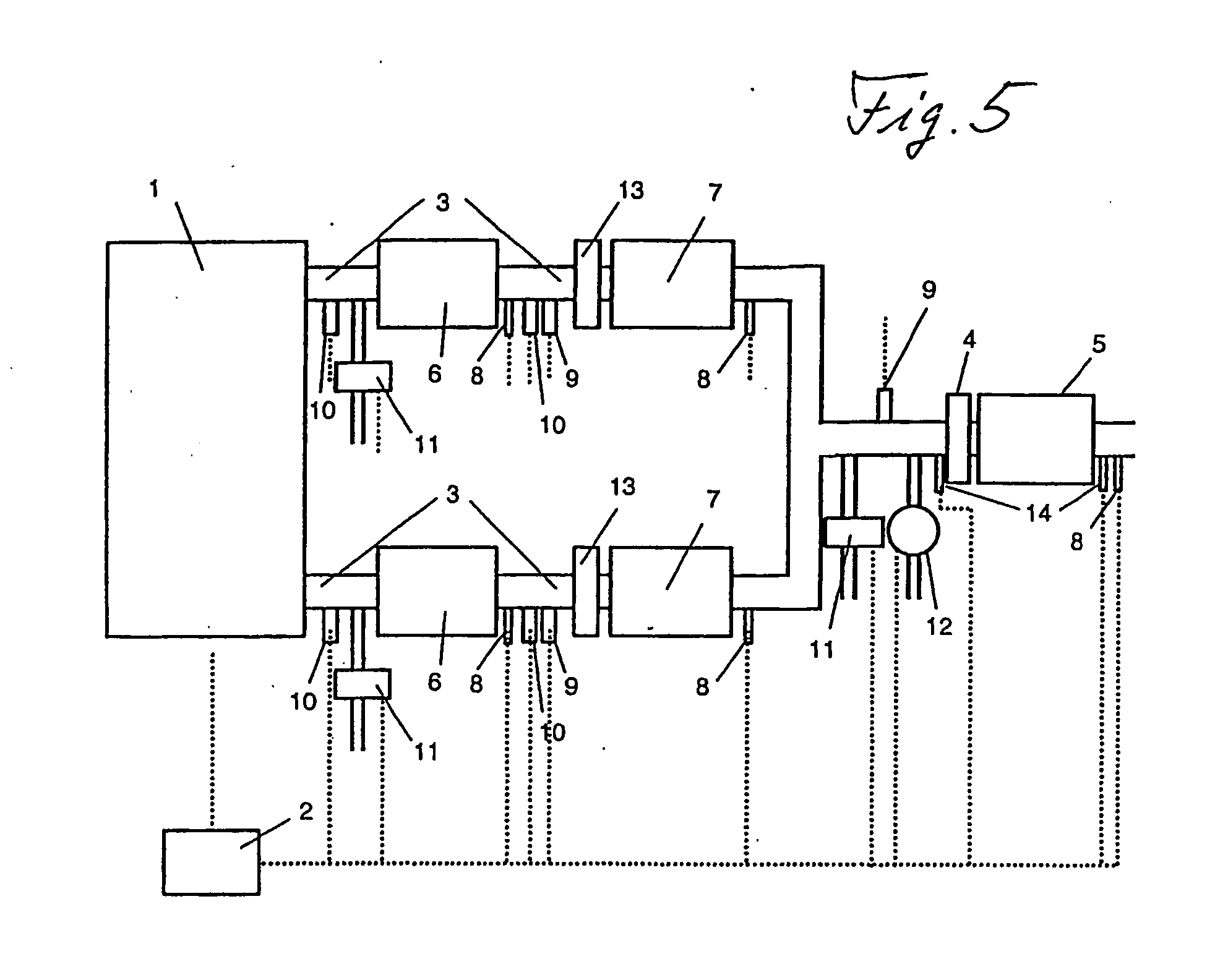
[0040] The exhaust gas aftertreatment installation illustrated in FIG. 1 includes, downstream of an internal combustion engine 1, as seen in the direction of flow of the exhaust gas, in an exhaust train 3, the following successive components: an oxidation catalytic converter 4, a particulate filter 5, an NOx storage catalytic converter 6, an NO2-producing catalytic converter 13, an SCR catalytic converter 7 and a further oxidation catalytic converter 4 as exhaust gas purification components. A control unit 2 is used to control the internal combustion engine 1, which may, for example, be a standard diesel or spark-ignition engine, and the exhaust gas aftertreatment installation. Furthermore, there are temperature sensors 8, NOx sensors 9, lambda sensors 10, devices 11 for supplying reducing agent downstream of the engine, a device 12 for supplying secondary air and pressure sensors 14 provided at suitable locations in the exhaust train 3, as shown...
PUM
| Property | Measurement | Unit |
|---|---|---|
| Flow rate | aaaaa | aaaaa |
| Ratio | aaaaa | aaaaa |
| Content | aaaaa | aaaaa |
Abstract
Description
Claims
Application Information
 - R&D
- Intellectual Property
- Life Sciences
- Materials
- Tech Scout
- Unparalleled Data Quality
- Higher Quality Content
- 60% Fewer Hallucinations
Browse by: Latest US Patents, China's latest patents, Technical Efficacy Thesaurus, Application Domain, Technology Topic, Popular Technical Reports.
© 2025 PatSnap. All rights reserved.Legal|Privacy policy|Modern Slavery Act Transparency Statement|Sitemap|About US| Contact US: help@patsnap.com


