
Multi-display supporting multi-view video object-based encoding apparatus and method, and object-based transmission/reception system and method using the same

a multi-view video and object-based encoding technology, applied in the field of multi-display supporting multi-view video object-based encoding apparatus and method, and the same object-based transmission/reception system and method, can solve the problem of increased image restoration and decoding time delay in the decoder, decreased transmission efficiency, and method is not suitable for frame-based time lag display mode. , to achieve the effect of simplifying the decoding process, reducing display delay, and enhancing

Inactive Publication Date: 2006-07-13
ELECTRONICS & TELECOMM RES INST
View PDF12 Cites 37 Cited by
  • Summary
  • Abstract
  • Description
  • Claims
  • Application Information

AI Technical Summary

Benefits of technology

[0013] It is, therefore, an object of the present invention to provide an object-based encoding apparatus and method, in which a pair of multi-view object images for the right eye and the left eyes, are separated on an even and odd field object, and encoded / decoded in an object-based encoding / decoding method using a shape and texture in order to give a stereoscopic effect to a multi-view video, and an object-based transmission / reception system using the object-based encoding apparatus and method.
[0015] In accordance with one aspect of the present invention, there is provided a multi-display supporting multi-view video object-based encoding method and applied to a multi-view video object-based encoding apparatus, comprising the steps of: a) receiving a left-eye image object video (L) and a right-eye image object video (R) from outside and abstracting a left object image (LS) and a right object image (RS), respectively, to abstract the shape information of a multi-view video; b) receiving the left-eye image object video (L) and the right-eye image object video (R) from outside, and the right / left shape (LS / RS) information transmitted from the step a), and separating the videos and the shape information into odd and even field objects to transmit only essential bit streams for a display mode of the multi-view video; c) compensating for the distortion of the shape information (shape of the (LO,LE) / (RO,RE) object) separated into odd and even fields; and d) receiving the compensated object-based information and the separated object-based information, forming four layers, i.e., LO stream, LE stream, RO stream and RE stream, and performing motion and disparity estimation based on shape encoding and shape texture to encode the object-based data that are separated into odd and even lines.
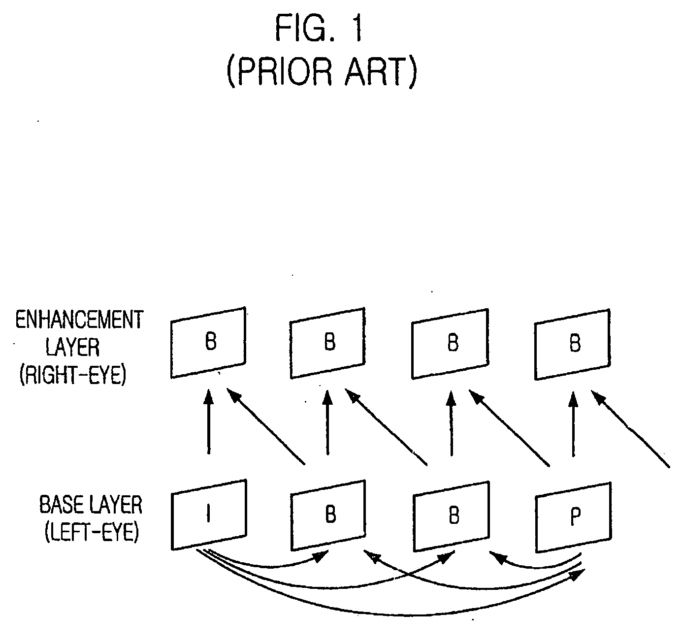
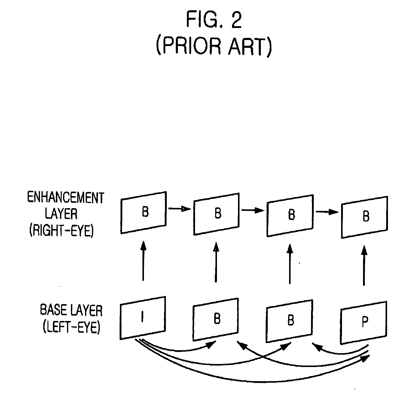
[0021] Before the encoding, each right and left object video images are divided into four field objects, odd lines and even lines for each video image, and encoded using the motion and disparity information of the shape and texture. Among the four encoded bit streams, only essential bit streams required by a user display mode is multiplexed and transmitted. In the receiving end, the received bit stream is demultiplexed and the image is restored based on the required user display mode, although part of the four bit streams are received. In case where the receiving end uses a three-dimensional video field-based time lag display mode and the two-dimensional video display mode, the MPEG-2 MVP-based binocular three-dimensional decoding apparatus, which performs decoding using all the two encoded bit streams outputted from the base layer and the enhancement layer, requires all the data to be transmitted thereto, although it should dismiss half of the transmitted data. Therefore, the transmission efficiency is decreased, and the decoding time becomes long.
[0022] On the other hand, the encoding apparatus of the present invention transmits only an essential field object, required by each user display for decoding, thereby minimizing the unnecessary channel occupation by inessential data transmission and the delay in decoding time.
[0026] Therefore, the object-based encoding / decoding apparatus has an effect of reducing display delay by enhancing transmission efficiency and simplifying the decoding process, because only essential bit streams are transmitted in accordance with the user display mode, i.e., two-dimensional monocular display mode, or binocular video field / frame-based time lag display mode so as to make the receiving end perform decoding.

Problems solved by technology

However, when the display mode of the receiving end is a three-dimensional field-based time lag display mode, which is adopted in most PCs, the methods of the two patents have problems that the amount of image restoration and the decoding time delay are increased in the decoder and the transmission efficiency is decreased, because the inessential data, the even field object of a left-eye image and the odd field image of a right-eye image, should be dismissed.
However, in case where frame estimation is performed, only motion information is used and disparity information is not considered.
Accordingly, this method is not proper to a frame-based time lag display mode, in which the right and left-eye images are displayed simultaneously.

Method used


Image

  • Multi-display supporting multi-view video object-based encoding apparatus and method, and object-based transmission/reception system and method using the same
  • Multi-display supporting multi-view video object-based encoding apparatus and method, and object-based transmission/reception system and method using the same
  • Multi-display supporting multi-view video object-based encoding apparatus and method, and object-based transmission/reception system and method using the same

Examples


Embodiment Construction

[0037] Other objects and aspects of the invention will become apparent from the following description of the embodiments with reference to the accompanying drawings, which is set forth hereinafter.

[0038]FIG. 3 is a block diagram describing a structure of a multi-view video object-based encoding apparatus in accordance with an embodiment of the present invention. As shown in the drawing, the multi-view video object-based encoding apparatus of the present invention includes a shape abstracting unit 31 for receiving a left-eye image object video (L) and a right-eye image object video (R) from outside and abstracting a left object image (LS), and a right object image (RS), respectively, to abstract the shape information of a multi-view three-dimensional video; a data separating unit 32 for receiving the left-eye image object video (L) and the right-eye image object video (R) from outside, and the right / left shape (LS / RS) information transmitted from the shape abstracting unit 31, and s...


PUM


Abstract

Provided are a multi-display supporting multi-view video object-based encoding apparatus and method, and an object-based transmission / reception system and method using the encoding apparatus and method. The encoding apparatus includes: a shape abstracting means for receiving right / left-eye image object video and abstracting right / left object image, respectively, to abstract the shape information of a multi-view video; a data separating means for receiving the right / left-eye image object video, and the right / left shape information, and separating them into odd-field objects and even field objects to transmit only the essential bit streams for a user display mode; a shape compensation means for compensating for the distortion of the shape information separated into odd and even fields; and an object-based encoding means for receiving the object-based information from the shape compensation means and the object-based information from the data separating means, forming four layers, and performing motion and disparity estimation to encode object-based data that are separated into odd and even lines.

Description

TECHNICAL FIELD [0001] The present invention relates to a multi-display supporting multi-view video object-based encoding apparatus and method, and an object-based transmission / reception system and method using the multi-view video object-based encoding apparatus and method; and, more particularly, to a multi-view video object-based encoding apparatus and method that can remove temporal and spatial redundancies by transmitting an essential encoded bit stream for a corresponding display mode and using a technology related to the motion and disparity of a shape or texture having an encodable structure, and an object-based transmission / reception system and method using the multi-view video object-based encoding apparatus and method. BACKGROUND ART [0002] A two-dimensional image is composed of monocular images on a single temporal axis, while a three-dimensional image is composed of multi-view images having two or more views, on a single temporal axis. Among the multi-view video encodin...

Claims


Application Information

Patent Timeline
IPC IPC(8): H04N11/04H04N13/04H04N15/00H04N11/02H04N7/12H04B1/66H04N7/24H04N13/00
CPCH04N19/597H04N19/20H04N19/61H04N13/00H04N19/17
Inventor CHOI, YUN JUNGCHOI, SUK-HEEYUN, KUNG JINLEE, JINHWANHAHM, YOUNG KWONANH, CHIETEUK
Owner ELECTRONICS & TELECOMM RES INST
Learn More