
Optical recording medium, optical recording/reproducing apparatus, optical, recording apparatus and optical reproducing apparatus, data recording/reproducing method for optical recording medium, and data recording method and data reproducing method

a recording medium and recording technology, applied in the field of optical recording mediums, can solve the problems of recording layers, sudden increase in absorption of laser beams in optically transparent layers, and difficulty in forming various functional layers, etc., to suppress the phenomenon of reproduction deterioration, excellent characteristics, and good characteristics

Inactive Publication Date: 2006-07-13
TDK CORPARATION
View PDF2 Cites 49 Cited by
  • Summary
  • Abstract
  • Description
  • Claims
  • Application Information

AI Technical Summary

Benefits of technology

The present invention provides an optical recording medium with a noble metal oxide layer that can perform super-resolution recording and reproducing using a laser beam with a shorter wavelength and an objective lens with a higher numerical aperture. The optical recording medium has excellent characteristics in both the recording and reproducing processes. The invention also provides an optical recording apparatus that can record and reproduce data into and from the super-resolution optical recording medium. The invention further provides a method for setting the optical recording medium with the optimal settings for recording and reproducing data. Overall, the invention provides a solution for improving the performance of optical recording media and their associated optical recording apparatus.

Problems solved by technology

In the advanced optical recording media, it is therefore difficult to form various functional layers such as a recording layer on the optically transparent substrate as in the existing optically recording media such as CDs or DVDs.
However, when the wavelength of the laser beam is made shorter, the absorption of the laser beam in the optically transparent layer may increase suddenly, or the aged deterioration of the optically transparent layer may increase.
It is therefore difficult to make the wavelength shorter.
In addition, it is also difficult to make the numerical aperture of the objective lens higher when difficulty in lens design, security of the tilt margin, and so on, are taken into consideration.
That is, it can be said that it is very difficult to make the beam spot diameter of the laser beam shorter.
Further, even if super-resolution reproducing can be attained, it is practically impossible to imagine how to set the configuration of layers, the material of each layer, and further the thickness of each layer or the like in order to obtain excellent signal characteristics, or how to set the power of the laser beam in order to obtain excellent signal characteristics.

Method used


Image

  • Optical recording medium, optical recording/reproducing apparatus, optical, recording apparatus and optical reproducing apparatus, data recording/reproducing method for optical recording medium, and data recording method and data reproducing method
  • Optical recording medium, optical recording/reproducing apparatus, optical, recording apparatus and optical reproducing apparatus, data recording/reproducing method for optical recording medium, and data recording method and data reproducing method
  • Optical recording medium, optical recording/reproducing apparatus, optical, recording apparatus and optical reproducing apparatus, data recording/reproducing method for optical recording medium, and data recording method and data reproducing method

Examples


example

[0116] An example of the present invention will be described below. However, the present invention is not limited to this example at all.

[0117] [Production of Sample]

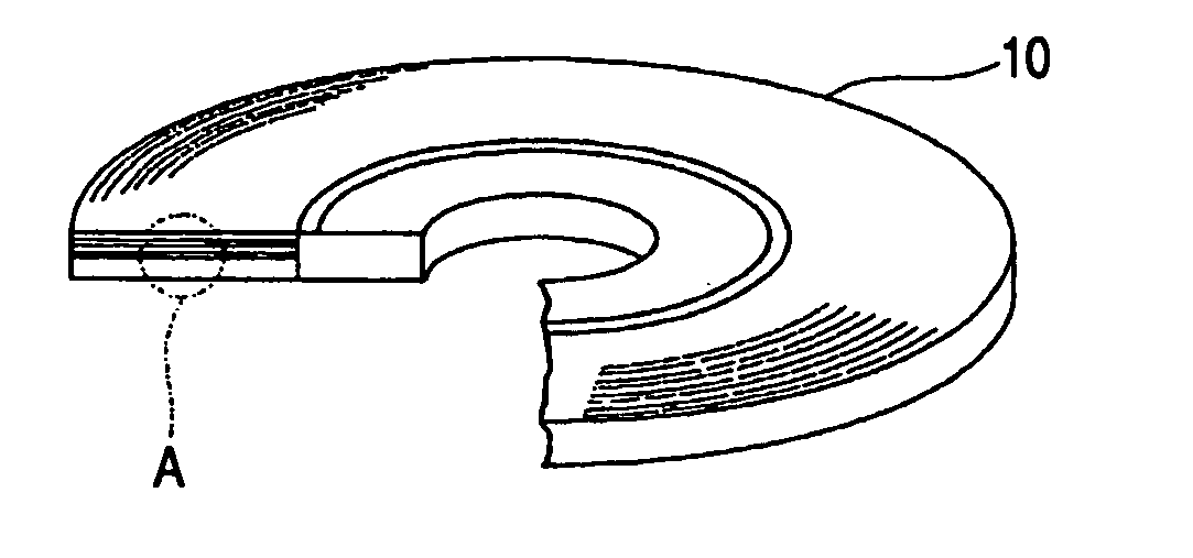
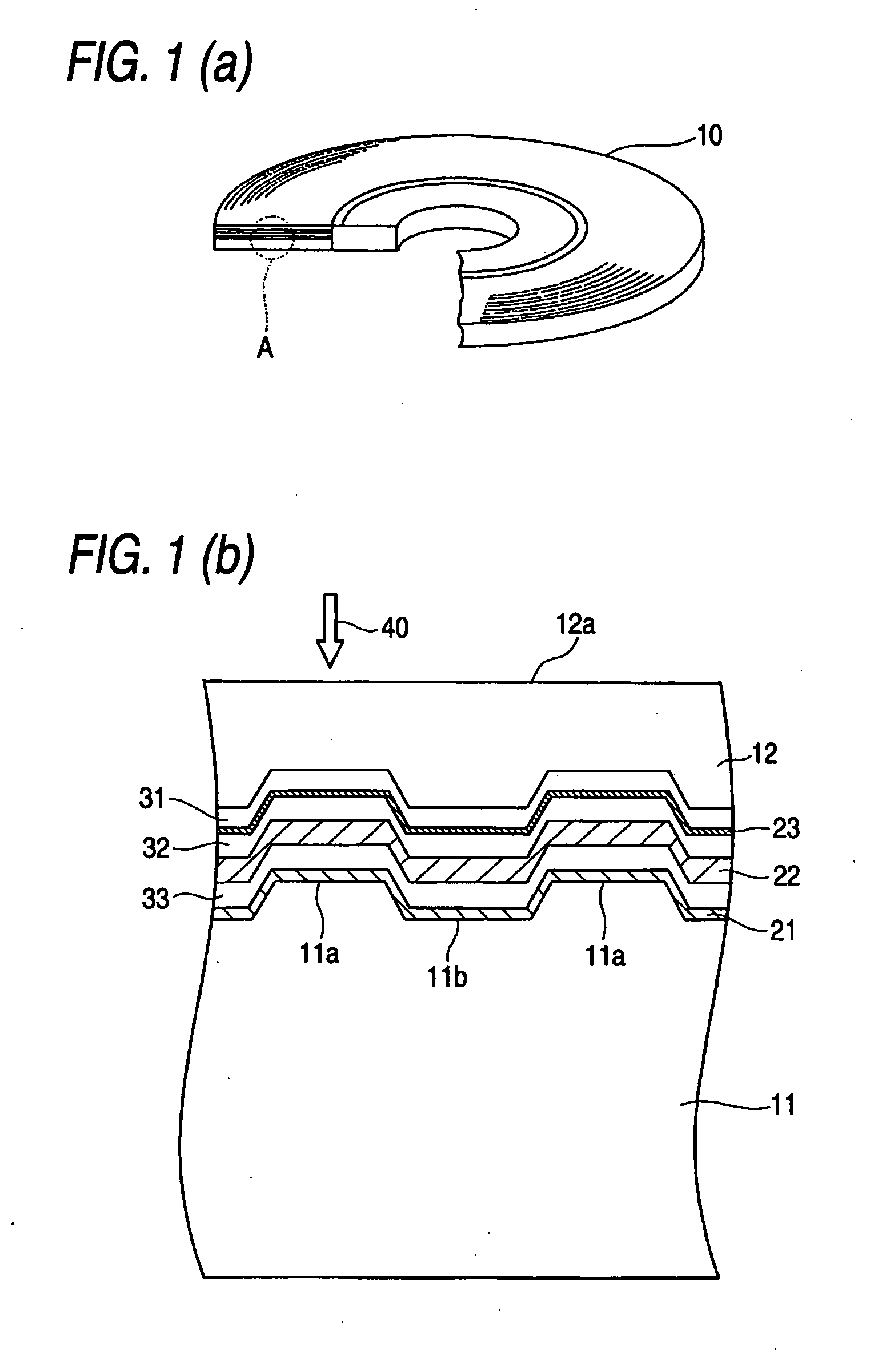
[0118] An optical recording medium sample having a structure in which the reflecting layer 21 was removed from the optical recording medium 10 shown in FIG. 1 was produced in the following method.

[0119] First, a disc-like substrate 11 made of polycarbonate and having a groove 11a and a land 11b formed on the surface was produced by an injection molding method to measure about 1.1 mm in thickness and about 120 mm in diameter.

[0120] Next, this substrate 11 was set in a sputtering apparatus. A dielectric layer 33 substantially made of a mixture of ZnS and SiO2 (mol ratio=about 80:20) and having a thickness of about 80 nm, a light absorbing layer 22 substantially made of AgaInbSbcTed (a=5.9, b=4.4, c=61.1, d=28.6) and having a thickness of about 60 nm, a dielectric layer 32 substantially made of a mixture of ZnS and SiO2...


PUM

PropertyMeasurementUnit
recording poweraaaaaaaaaa

Abstract

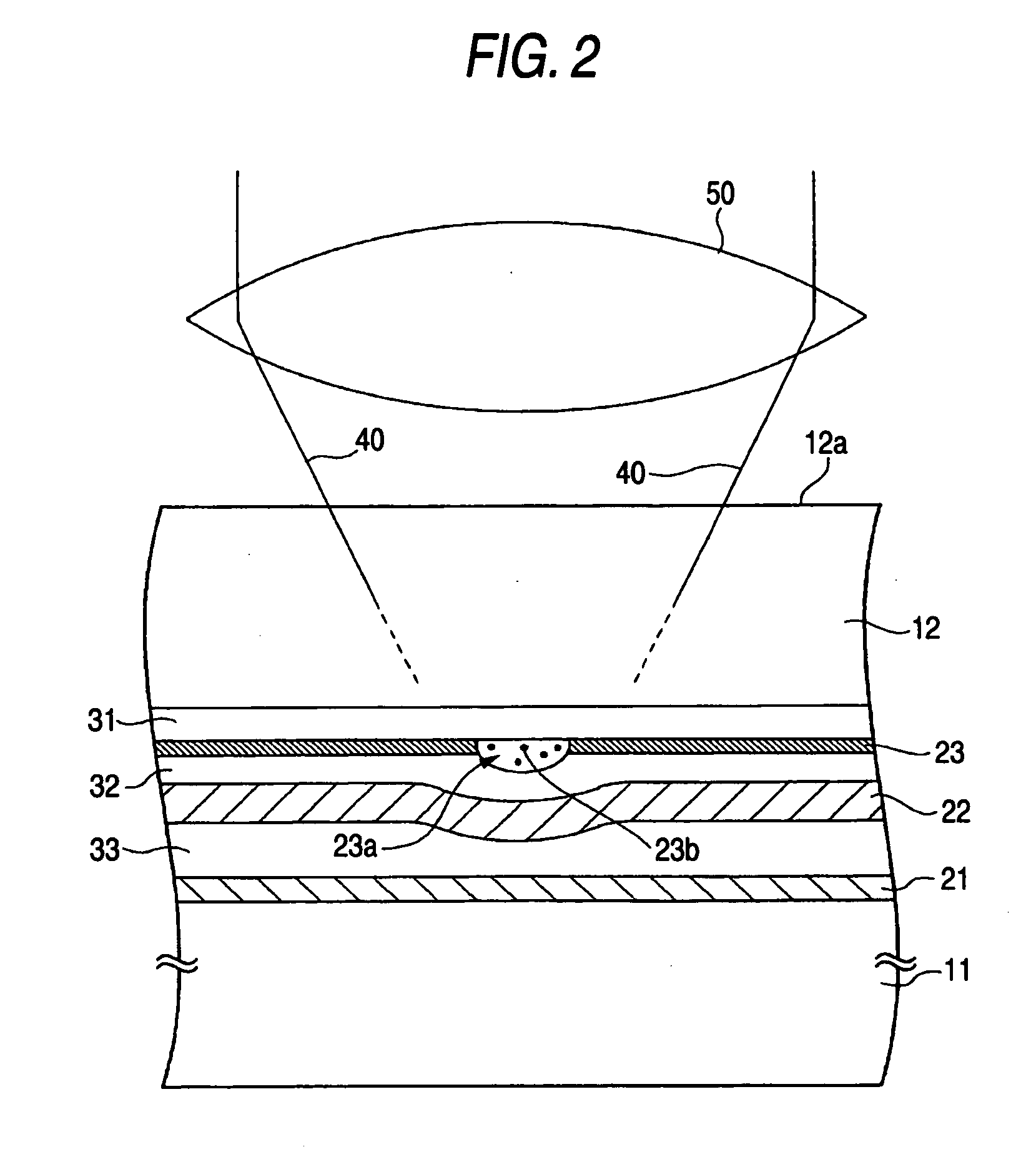
An optical recording medium 10 having a substrate 11, an optically transparent layer 12, and a first dielectric layer 31, a noble metal oxide layer 23, a second dielectric layer 32, a light absorbing layer 22, a third dielectric layer 33 and a reflecting layer 21 which are disposed between the optically transparent layer 12 and the substrate 11, records and reproduces data into and from the optical recording medium 10 by irradiating the optical recording medium 10 with a laser beam 40 from the optically transparent layer 12 side. λ / NA is set to be not longer than 640 nm when λ designates a wavelength of the laser beam 40 and NA designates a numerical aperture of an objective lens, and setting is done as Pw×0.1≦Pr≦Pw×0.5 when Pw and Pr designate recording power and reproducing power of the laser beam 40 respectively, while a recording mark train including recording marks each having a length not larger than λ / 4 NA is recorded and data are reproduced from the recording mark train.

Description

TECHNICAL FIELD [0001] The present invention relates to an optical recording medium, and particularly relates to a super-resolution type optical recording medium which can form minute recording marks smaller than a resolution limit and reproduce data from such recording marks. In addition, the present invention relates to an optical recording / reproducing apparatus, an optical recording apparatus and an optical reproducing apparatus, and particularly relates to an optical recording / reproducing apparatus, an optical recording apparatus and an optical reproducing apparatus which can record and / or reproduce data into and / or from a super-resolution type optical recording medium. Further, the present invention relates to a method for recording / reproducing data into / from an optical recording medium, a method for recording data into an optical recording medium and a method for reproducing data from an optical recording medium, and particularly relates to a method for recording / reproducing d...

Claims


Application Information

Patent Timeline
Patent Type & Authority Applications(United States)
IPC IPC(8): G11B7/24G11B7/243G11B7/0045G11B7/005G11B7/125
CPCG11B7/00452G11B7/00454G11B7/24038G11B7/24065G11B7/243G11B2007/24304G11B2007/2432G11B2007/25706G11B2007/25715G11B7/0045G11B7/005G11B7/126G11B7/257
Inventor KIKUKAWA, TAKASHIFUKUZAWA, NARUTOSHIKOBAYASHI, TATSUHIRO
Owner TDK CORPARATION
Learn More