
System for collecting information on biological particles

Inactive Publication Date: 2006-07-13
BAY BIOSCI
View PDF6 Cites 42 Cited by
  • Summary
  • Abstract
  • Description
  • Claims
  • Application Information

AI Technical Summary

Benefits of technology

[0007] One of the aspects of the present invention has a purpose to provide a flow cytometer capable of adjusting the optical axis in a simple manner, and also the flow cytometer capable of detecting the biological features of the biological particles in a more precise manner.

Problems solved by technology

However, the particles may be stuck at the orifice of the flow chamber 204, or the flow may be disturbed or inclined.
In those cases, while the flow chamber 204 has to be removed from the system and cleaned, the optical alignment (including, for example, an irradiation position and a focal length of the laser beam, a position and an angle of a nozzle, an irradiation position and a focal length of the objective lens) must be adjusted, such adjustment task is considerably cumbersome and complicated.
Also, it is difficult to downsize the optics used in the system since those lens incorporated therein have a high aperture ratio.
However, such a small lens cannot collimate the fluorescent light sufficiently.
Also, multiple collective lens often have to be combined in many cases, therefore, improvement of sensibility cannot be expected because of air layers interposed between the adjacent lens.
To this end, it was impossible to downsize the optics of the system.

Method used


Image

  • System for collecting information on biological particles
  • System for collecting information on biological particles
  • System for collecting information on biological particles

Examples


Embodiment Construction

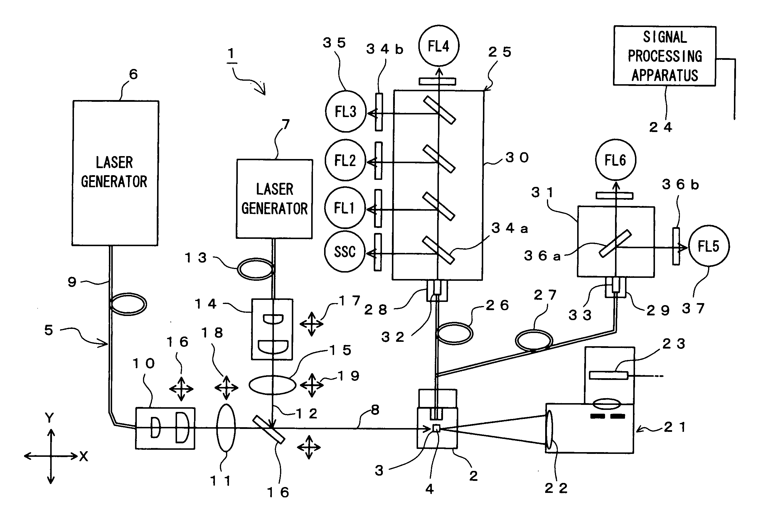
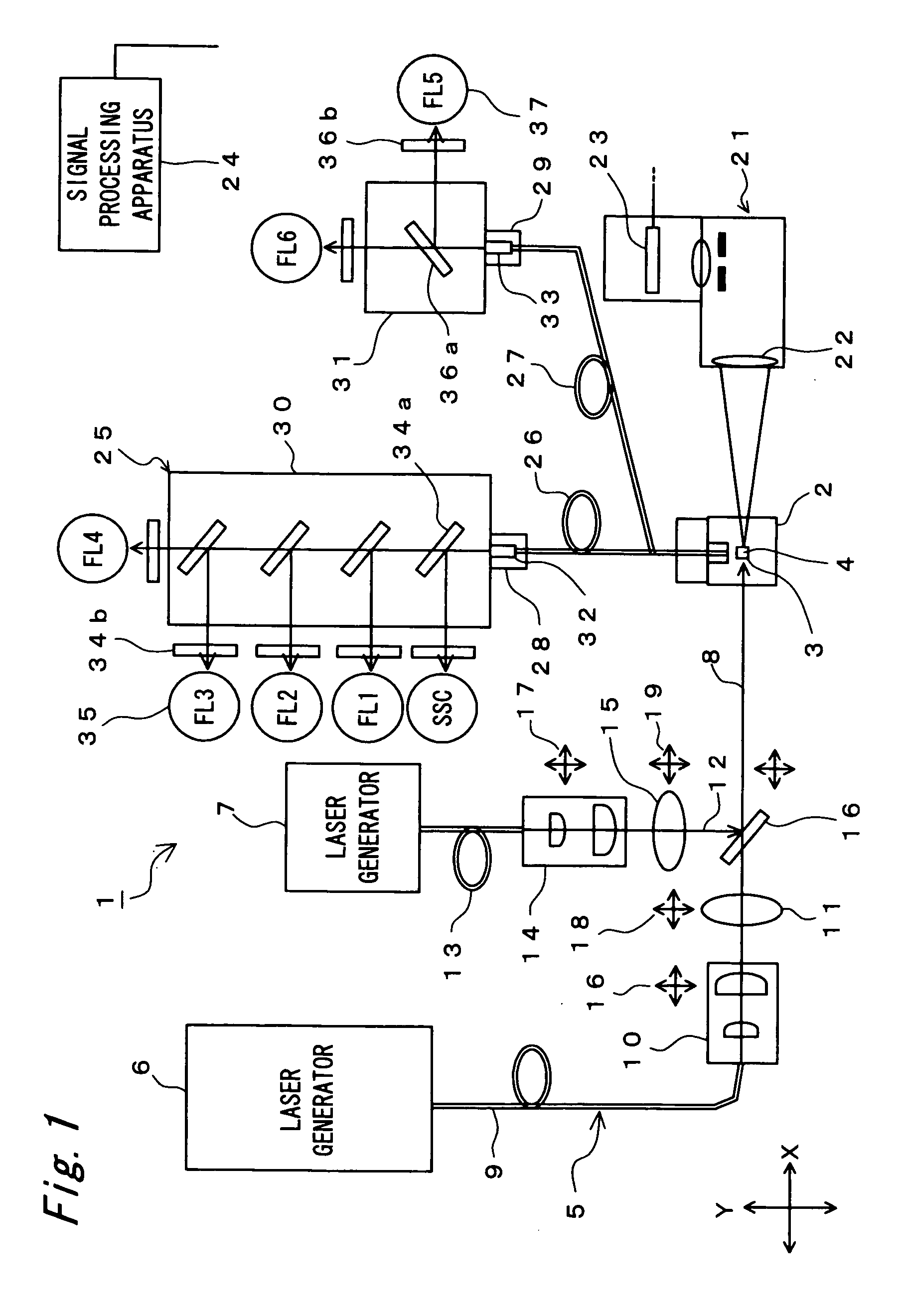
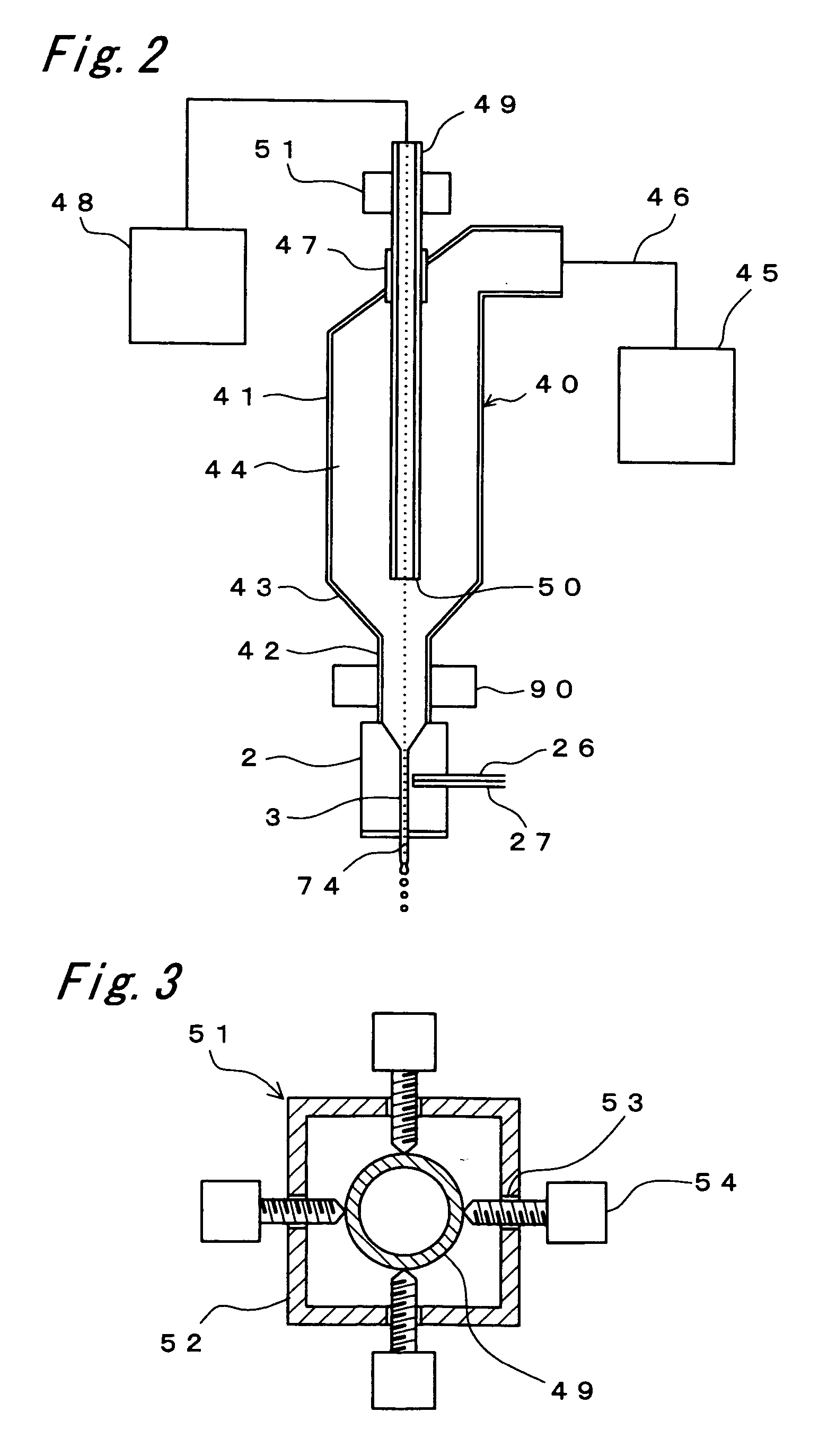
[0024] Referring to drawings, a flow cytometry system (flow cytometer) according to the present invention will be described herein.

I. Optical Components:

[0025]FIG. 1 illustrates several optical elements of the flow cytometer. As shown in FIG. 1, the flow cytometer 1 includes a flow-path block (path-defining structure) 2 for defining a thin flow path, through which fluid containing biological particles (cells or chromosomes) dyed with fluorescent pigment or fluorochrome antibody, typically consisting of fluid suspension containing cells and sheath fluid, runs. An irradiation apparatus 5 of the present invention includes two excitation light sources 6, 7 for irradiating light onto the sheath flow 4 running through the flow path 3 defined by the flow-path block 2. Preferably, laser-beam generators are used as the light sources for generating the laser beam having wavelengths different from each other. For instance, a first laser generator 6 is used as the first light source to gener...


PUM


Abstract

A system (1) for collecting biological information on a dyed biological particle (cell or chromosome) by irradiating light onto liquid containing the dyed biological particles and for detecting information light therefrom is provided according to the present invention. The system includes a path-defining structure (2) of transparent material defining a flow path (3) through which the liquid containing the dyed biological particles runs, an irradiation apparatus (5) for irradiating light onto the particles passing through the flow path (3), a first detecting apparatus (21) for detecting first information light obtained from the irradiated particle, and a second detecting apparatus (25) for detecting second information light obtained from the irradiated particle. At least one of the first and second detecting apparatuses (21, 25) includes one or more fiber optics (26, 27), of which one ends (61, 62) are arranged adjacent the flow path (3) so as to collect the information light.

Description

TECHNICAL FIELD [0001] The present invention relates to a system for collecting biological information on biological particles such as cells and chromosomes. In particular, the present invention relates to a flow cytometer or a cell sorter which forms a laminar flow containing cells or chromosomes dyed with pigment material such as fluorochrome, irradiates light such as laser beam on the laminar flow to detect information light (scattered light and fluorescent light), converts optical information within the information light into,electrical signals to collect biological information on cells or chromosomes, and if desired, extracts a group of particular cells or chromosomes based upon the biological information. BACKGROUND ART [0002] As the biotechnology has been developed, a flow cytometer is more commonly used in the fields of medicine and biology for automatic analysis and fractionation of cells or chromosomes (which are referred to simply as “cells”). The flow cytometer forms a s...

Claims


Application Information

Patent Timeline
IPC IPC(8): G01N21/00G01N15/14G01N33/48G01N21/64G01N33/483
CPCG01N15/1456G01N2015/1472G01N2015/1477G01N15/149
Inventor KANDA, MASAHIKO
Owner BAY BIOSCI
Learn More