
Projection control system, projector and projection control method

a technology of projection control and projector, applied in the direction of printers, instruments, camera focusing arrangement, etc., can solve the problems of image quality deterioration, image distortion (keystone distortion), and processing tim

Inactive Publication Date: 2006-07-13
SEIKO EPSON CORP
View PDF16 Cites 33 Cited by
  • Summary
  • Abstract
  • Description
  • Claims
  • Application Information

AI Technical Summary

Benefits of technology

[0105] This enables the processing section to adjust the size of the projection area to a desired size by means of hardware, so that the projection section can project an image which deteriorates in image quality to only a small extent in comparison with the case of adjusting the size of the projection area by means of software.

Problems solved by technology

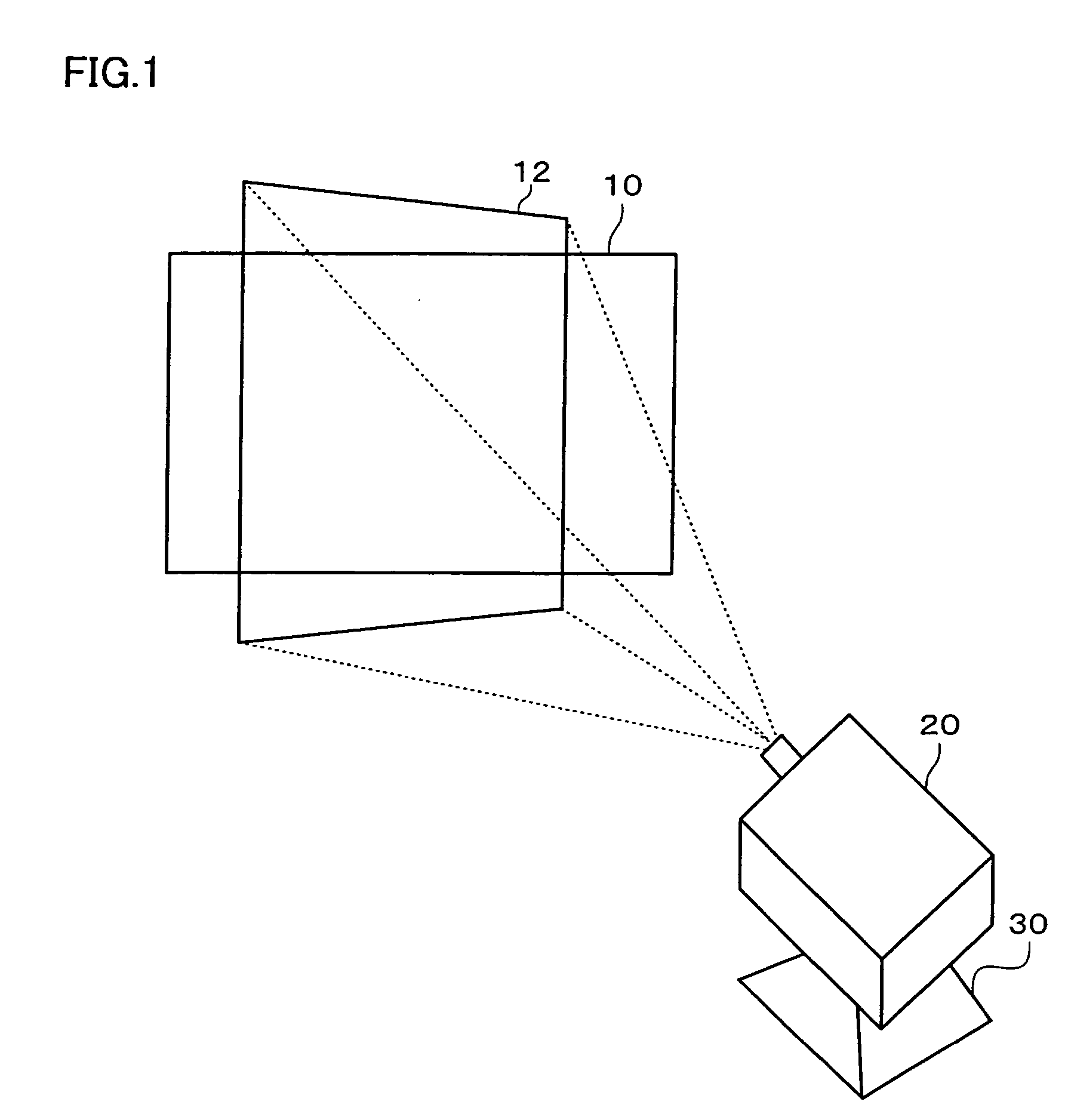
When a projector projects an image onto a screen or the like, image distortion (keystone distortion) occurs depending on the angle formed by a projection target area on the screen or the like and projection light from the projector.
The software correction can be performed at low cost, but causes the image quality to deteriorate.
However, processing takes time when using this method of adjusting the angle of view by expanding or reducing the projected image by using the zooming function of the projection lens until the projected image reaches the detected endpoints of the screen as disclosed in JP-A-2000-241874.
Moreover, the method disclosed in JP-A-2000-241874 cannot be applied when the aspect ratio of the screen differs from the aspect ratio of the projected image.
However, JP-A-2000-241874 does not disclose detailed processing.

Method used


Image

  • Projection control system, projector and projection control method
  • Projection control system, projector and projection control method
  • Projection control system, projector and projection control method

Examples


Embodiment Construction

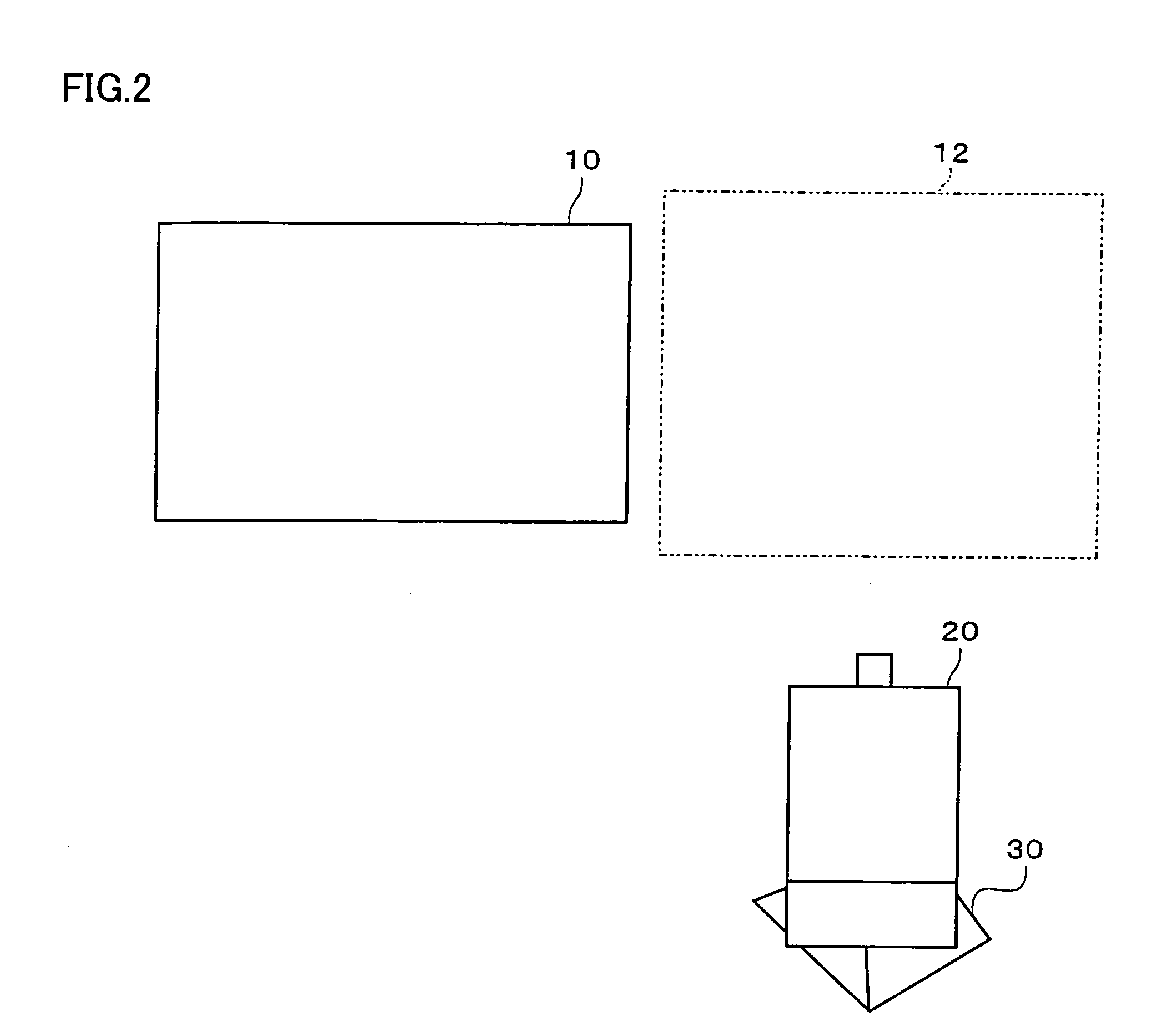
[0045] The invention may provide a projection control system, a projector, and a projection control method capable of reducing deterioration of the image quality caused by image distortion correction and more universally preventing occurrence of image distortion.

[0046] A projection control system according to one embodiment of the invention includes:

[0047] a projection angle deriving section which generates projection angle information indicating an angle formed by a projection target area and projection light projected onto the projection target area;

[0048] a projection distance deriving section which generates projection distance information indicating a distance from an aim area in the projection target area to a projection section which projects the projection light;

[0049] a control information generation section which generates direction control information for aligning a projection direction of the projection light with a normal direction of the projection target area base...


PUM


Abstract

A projector includes a projection angle deriving section which generates projection angle information indicating an angle formed by a projection target area and projection light projected onto the projection target area; a projection distance deriving section which generates projection distance information indicating a distance from an aim area in the projection target area to a projection section which projects the projection light; a control information generation section which generates direction control information for aligning a projection direction of the projection light with a normal direction of the projection target area based on the projection angle information, and generates projection section control information for controlling the projection section so that the projection light is projected onto the aim area based on the projection distance information; a pedestal driver section which drives a pedestal which adjusts the projection direction of the projection light based on the direction control information; a control section which controls the projection section based on the projection section control information; and the projection section.

Description

[0001] Japanese Patent Application No. 2005-2311, filed on Jan. 7, 2005, is hereby incorporated by reference in its entirety. BACKGROUND OF THE INVENTION [0002] The present invention relates to a projection control system, a projector, and a projection control method capable of deriving a projection angle based on sensing information and adjusting a projection direction or the like based on the projection angle. [0003] When a projector projects an image onto a screen or the like, image distortion (keystone distortion) occurs depending on the angle formed by a projection target area on the screen or the like and projection light from the projector. [0004] In this case, the projector performs image processing of eliminating image distortion by software correction. [0005] The software correction can be performed at low cost, but causes the image quality to deteriorate. [0006] Therefore, a method of eliminating image distortion by hardware correction has been proposed aiming at improvin...

Claims


Application Information

Patent Timeline
Patent Type & Authority Applications(United States)
IPC IPC(8): G03B21/00
CPCG03B21/14H04N9/3185G03B21/142
Inventor MATSUDA, HIDEKIKOBAYASHI, MASANOBUWADA, OSAMU
Owner SEIKO EPSON CORP
Learn More