
Piezoelectric liquid inertia vibration eliminator

a liquid inertia and vibration eliminator technology, applied in the direction of shock absorbers, machine supports, transportation and packaging, etc., can solve the problems of toxic and high-corrosion mercury

Active Publication Date: 2006-07-13
BELL HELICOPTER TEXTRON INC
View PDF36 Cites 58 Cited by
  • Summary
  • Abstract
  • Description
  • Claims
  • Application Information

AI Technical Summary

Benefits of technology

[0013] It is another object of the present invention to provide a vibration isolator that allows active tuning of the isolator, as well as, simultaneous vibration treatment of multiple harmonics.
[0014] It is yet another object of the present invention to provide a vibration isolator that allows active tuning of the isolator, as well as, active “negative” damping which results in near zero vibration transmissibility.
[0015] It is yet another object of the present invention to provide a vibration isolator that allows active tuning of the isolator by utilizing piezoceramic elements for actuation.

Problems solved by technology

The original dense, low-viscosity fluid contemplated by Halwes '607 was mercury, which is toxic and highly corrosive.

Method used


Image

  • Piezoelectric liquid inertia vibration eliminator
  • Piezoelectric liquid inertia vibration eliminator
  • Piezoelectric liquid inertia vibration eliminator

Examples


Embodiment Construction

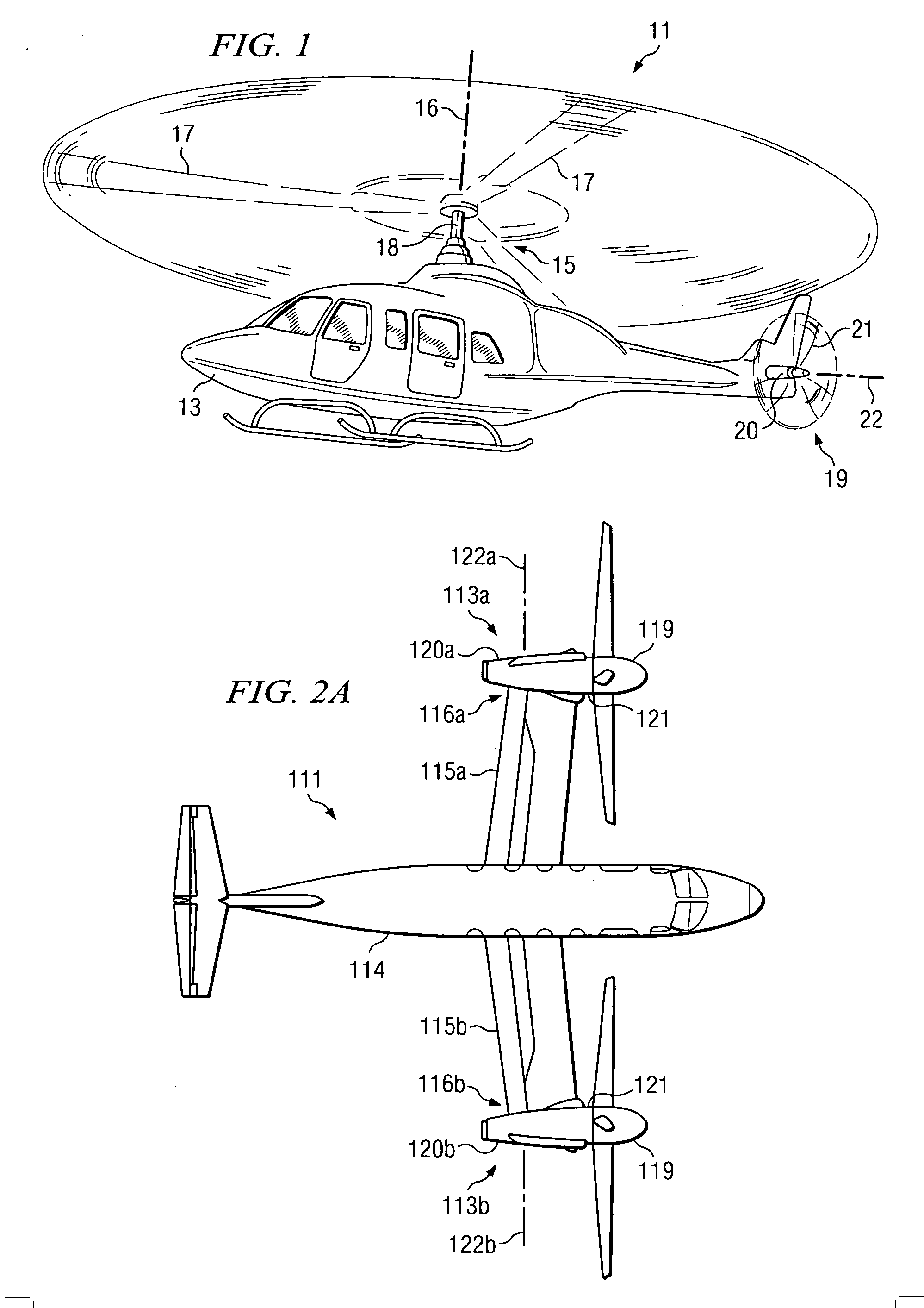
[0059] Referring to FIG. 1 in the drawings, a helicopter 11 according to the present invention is illustrated. Helicopter 11 has a fuselage 13 and a main rotor assembly 15, including main rotor blades 17 and a main rotor shaft 18. Helicopter 11 has a tail rotor assembly 19, including tail rotor blades 21 and a tail rotor shaft 20. Main rotor blades 17 generally rotate about a vertical axis 16 of main rotor shaft 18. Tail rotor blades 21 generally rotate about a lateral axis 22 of tail rotor shaft 20. Helicopter 11 also includes a vibration isolation system according to the present invention for isolating fuselage 13 or other portions of helicopter 11 from mechanical vibrations, such as harmonic vibrations, which are associated with the propulsion system and which arise from the engine, transmission, and rotors of helicopter 11.

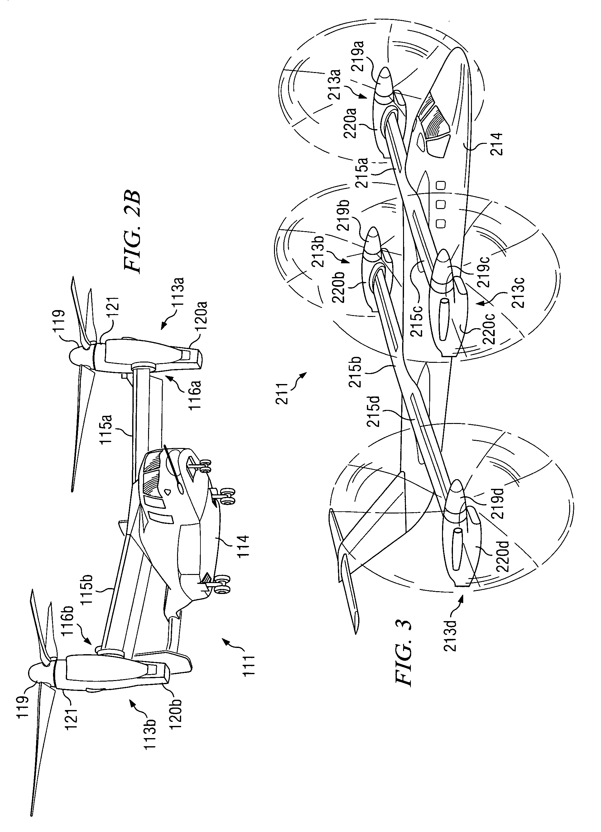
[0060] The present invention may also be utilized on other types of rotary wing aircraft. Referring now to FIGS. 2A and 2B in the drawings, a tilt rotor airc...


PUM


Abstract

A tunable vibration isolator with active tuning elements having a housing, fluid chamber, and at least one tuning port. A piston is resiliently disposed within the housing. A vibration isolation fluid is disposed within the fluid chambers and the tuning ports. The tunable vibration isolator may employ either a solid tuning mass approach or a liquid tuning mass approach. The active vibration elements are preferably solid-state actuators.

Description

TECHNICAL FIELD [0001] The present invention relates in general to active vibration control. More specifically, the present invention relates to methods and apparatuses for isolating mechanical vibrations in structures or bodies that are subject to harmonic or oscillating displacements or forces. The present invention is well suited for use in the field of aircraft, in particular, helicopters and other rotary wing aircraft. DESCRIPTION OF THE PRIOR ART [0002] For many years, effort has been directed toward the design of apparatus for isolating a vibrating body from transmitting its vibrations to another body. Such apparatuses are useful in a variety of technical fields in which it is desirable to isolate the vibration of an oscillating or vibrating device, such as an engine, from the remainder of the structure. Typical vibration isolation and attenuation devices (“isolators”) employ various combinations of the mechanical system elements (springs and mass) to adjust the frequency res...

Claims


Application Information

Patent Timeline
Patent Type & Authority Applications(United States)
IPC IPC(8): F16F7/10B64C27/00F16F7/108F16F13/08F16F13/24F16F13/26F16F15/00F16F15/027
CPCB64C27/001B64C2027/005F16F7/1005F16F7/1034F16F15/027F16F13/08F16F13/24F16F13/26F16F15/005F16F7/108
Inventor SMITH, MICHAELRSTAMPA, FRANKBLEE, TAEOHHEVERLY, DAVIDE JR.PASCAL, ROBERTJ
Owner BELL HELICOPTER TEXTRON INC
Learn More