Heat exchanging tube and heat exchanger

a technology of heat exchanger and heat exchanger, which is applied in the direction of indirect heat exchanger, refrigeration components, light and heating apparatus, etc., can solve the problems of reduced inherent heat exchange performance, reduced heat exchange performance, and weight reduction, so as to improve heat exchange performance and reduce passage resistance , the effect of reducing the weigh

Inactive Publication Date: 2006-07-13
KEIHIN THERMAL TECH CORP
View PDF8 Cites 12 Cited by
  • Summary
  • Abstract
  • Description
  • Claims
  • Application Information

AI Technical Summary

Benefits of technology

[0012] It is an object of the present invention to provide a heat exchanging tube capable of improving heat exchanging performance and decreasing passage resistance while decreasing the weight and obtaining enough pressure resistance.
[0013] It is another object of the present invention to provide a heat exchanger capable of improving heat exchanging performance and decreasing passage resistance while decreasing the weight and obtaining enough pressure resistance.

Problems solved by technology

Such methods for decreasing weight are, however, considered to be reached a limit, and a further attempt to decrease the weight based on such methods causes decreased inherent heat exchanging performance.
For example, if the tube height is set to be lower, the inner perimeter of each refrigerant flow path becomes shorter, causing deteriorated heat releasing performance.
Further, if the fin thickness is set to be thinner, the temperature difference between the portion of the fin which is in contact with the tube and the central portion of the fin becomes larger, causing deteriorated heat releasing performance.

Method used


Image

  • Heat exchanging tube and heat exchanger
  • Heat exchanging tube and heat exchanger
  • Heat exchanging tube and heat exchanger

Examples


example 1

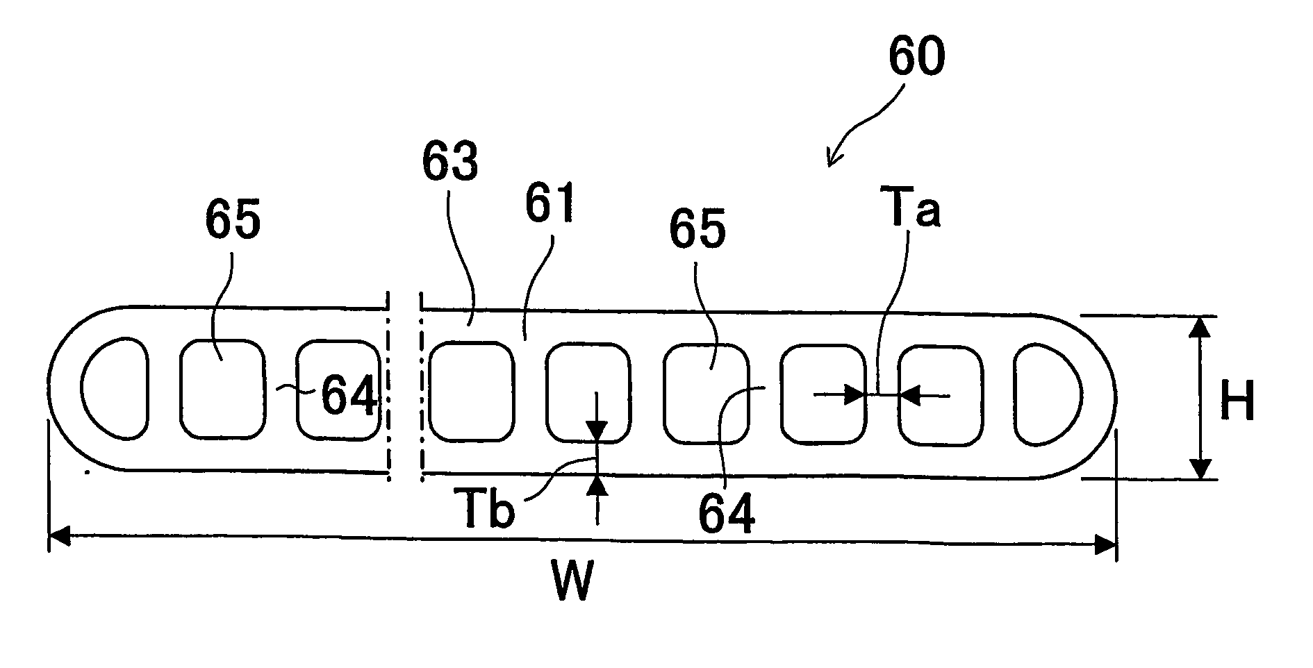
[0068] Heat exchanging tubes according to the aforementioned embodiment (shown in. FIGS. 3 and 4) were manufactured. As shown in Table 1, the total cross-sectional area Ac of the refrigerant passages was set to be 5.29 mm2, the total cross-sectional area At of the tube main body was set to be 8.92 mm2, the total inner perimeter P of the refrigerant passages was set to be 64.1 mm, the external perimeter L of the tube main body was set to be 17.3 mm, the total cross-sectional area of the refrigerant passages relative to the total cross-sectional area of the tube main body Ac / At was set to be 59%, the total inner perimeter of the refrigerant passages relative to the external perimeter of the tube main body P / L was to set to 371%, the number of the refrigerant passages was set to be 28 pieces, the tube height H was set to be 1.15 mm, the tube width W was set to be 8 mm, the total inner perimeter of the refrigerant passages relative to the tube width P / W was set to be 801%, the number of...

example 2

[0070] As shown in Table 1, in the same manner as in Example 1, heat exchanging tubes were manufactured such that Ac was set to 8.36 mm2, At was set to be 13.5 mm2, P was set to be 101.2 mm, L was set to be 25.3 mm, Ac / At was set to be 62%, P / L was set to be 400%, N was set to be 44 pieces, H was set to be 1.15 mm, W was set to be 12 mm, P / W was set to be 843%, N / W was set to be 3.67 pieces / mm, Ta was set to be 0.06 mm, Tb was set to be 0.1 mm. Furthermore, a heat exchanger was manufactured by using these heat exchanging tubes.

example 3

[0071] As shown in Table 1, in the same manner as in Example 1, heat exchanging tubes were manufactured such that Ac was set to 11.3 mm2, At was set to be 18.1 mm2, P was set to be 131.8 mm, L was set to be 33.3 mm, Ac / At was set to be 63%, P / L was set to be 396%, N was set to be 57 pieces, H was set to be 1.15 mm, W was set to be 16 mm, P / W was set to be 824%, N / W was set to be 3.56 pieces / mm, Ta was set to be 0.06 mm, Tb was set to be 0.1 mm. Furthermore, a heat exchanger was manufactured by using these heat exchanging tubes.


PUM


Abstract

A heat exchanging tube is provided with a flat tube main body having a predetermined length and a plurality of refrigerant passages extending in a tube longitudinal direction and arranged in a tube widthwise direction. The following relational equations (a) to (c) are satisfied: W=6 to 18 mm . . . (a); Ac / At×100=50 to 70% . . . (b) and P / L×100=350 to 450% . . . (c), where “W” is a width of the tube main body, “Ac” is a total cross-sectional area of the refrigerant passages, “At” is a total cross-sectional area of the tube main body ( including the refrigerant passages), “L” is an external perimeter of the tube main body and “P” is a total inner perimeter of the refrigerant passages. With this tube, enough pressure strength can be obtained and the passage resistance can be decreased while keeping the light weight, and further the heat exchanging performance can be improved.

Description

[0001] Priority is claimed to Japanese Patent Application No. 2002-290180, filed on Oct. 2, 2002, U.S. Provisional Patent Application No. 60 / 421,082, filed on Oct. 25, 2002 and Japanese Patent Application No. 2003-327179, filed on Sep. 19, 2003, the disclosure of which are incorporated by reference in their entireties. CROSS-REFERENCE TO RELATED APPLICATIONS [0002] This application is an application filed under 35 U.S.C. §111(a) claiming the benefit pursuant to 35 U.S.C. §119(e)(1) of the filing date of Provisional Application No.60 / 421,082 filed on Oct. 25, 2002 pursuant to 35 U.S.C. §111(b).TECHNICAL FIELD [0003] The present invention relates to a heat exchanger such as a condenser or an evaporator for use in a refrigeration cycle of automobile air-conditioners, household air-conditioners, refrigerators, electronics device coolers or the like, and also relates to a heat exchanging tube thereof. BACKGROUND ART [0004] The following description sets forth the inventor's knowledge of ...

Claims


Application Information

Patent Timeline
Patent Type & Authority Applications(United States)
IPC IPC(8): F28F1/00F28D1/053F28F1/02
CPCF25B39/00F25B2500/01F28D1/05383F28D2021/0029F28F1/022F28F1/02F28F1/10
Inventor TAKE, KOICHIRO
Owner KEIHIN THERMAL TECH CORP
Why Eureka
Try Eureka