
Method for forming salicide layer in semiconductor device

a technology of semiconductor devices and silicide layers, which is applied in the direction of semiconductor devices, basic electric elements, electrical equipment, etc., can solve the problems of limiting the speed of a very large scale integration (vlsi) circuit, affecting the production efficiency of semiconductor devices, so as to reduce processing steps and simplify the manufacturing of integrated circuits. , the effect of preventing plasma damage to exposed silicon surfaces

Inactive Publication Date: 2006-07-06
DONGBU ELECTRONICS CO LTD
View PDF2 Cites 4 Cited by
  • Summary
  • Abstract
  • Description
  • Claims
  • Application Information

AI Technical Summary

Benefits of technology

[0016] The present invention may provide a method for forming a silicide layer in a semiconductor device, which simplifies the manufacture of an integrated circuit by reducing processing steps.
[0017] The present invention may provide a method for forming a silicide layer in a semiconductor device that avoids dry etching, thereby preventing plasma damage to exposed silicon surfaces, and avoids wet etching, thereby preventing an undercutting of an oxide spacer.

Problems solved by technology

In semiconductor devices such as MOSFETs, the minimum surface resistance of a thin polysilicon gate or a shallow source-drain diffusion region is about 10-20 ohms / square, which results in an inefficient interconnection and limits the speed of a very large scale integration (VLSI) circuit.
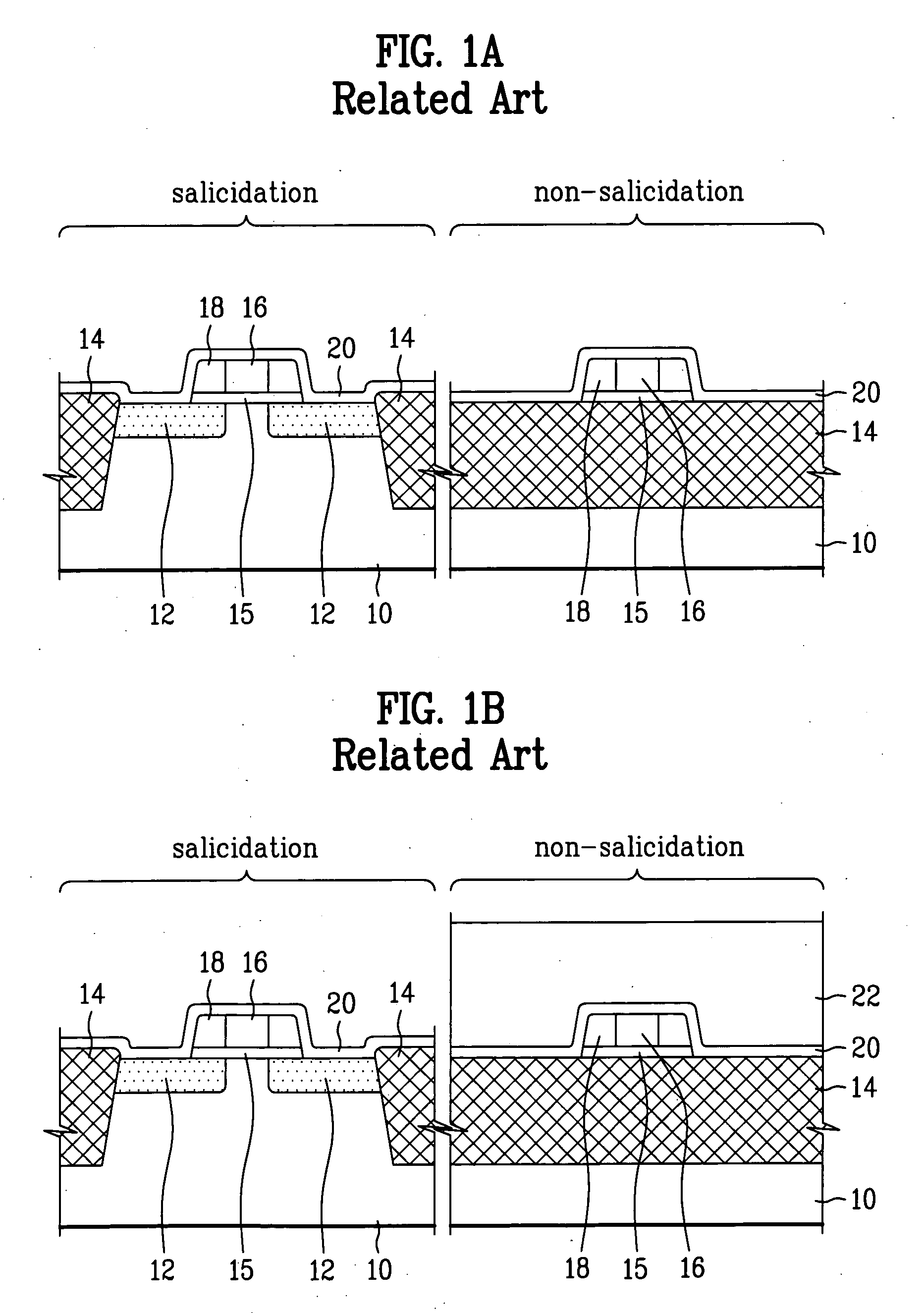
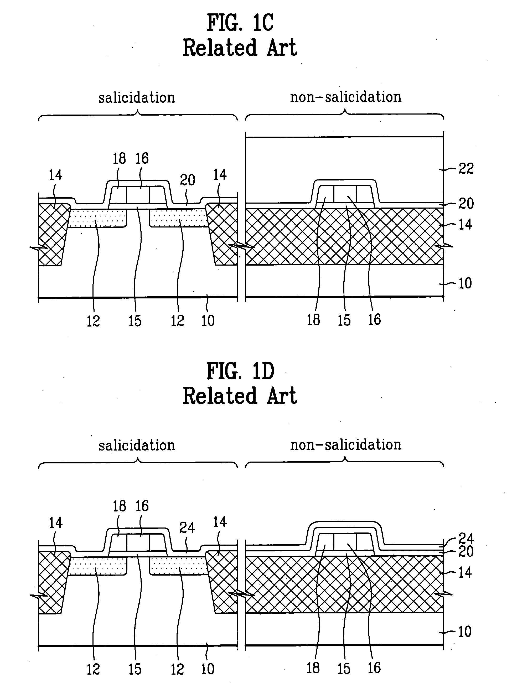
Furthermore, in the case of dry etching, exposed silicon surfaces may be damaged by plasma, and in the case of wet etching, the undercutting 28 of the oxide spacer may occur, as shown in FIG. 2.

Method used


Image

  • Method for forming salicide layer in semiconductor device
  • Method for forming salicide layer in semiconductor device
  • Method for forming salicide layer in semiconductor device

Examples


Embodiment Construction

[0025] Reference will now be made in detail to exemplary embodiments of the present invention, examples of which are illustrated in the accompanying drawings. Wherever possible, like reference designations will be used throughout the drawings to refer to the same or similar parts.

[0026]FIGS. 3A-3D respectively show steps of a salicide forming method according to one embodiment of the present invention, which simultaneously forms an electrical contact on top of a gate electrode and a source-drain diffusion region and carried out after formation of the gate electrode and the source-drain diffusion region on a semiconductor substrate.

[0027] As shown in FIG. 3A, a gate electrode 16, a source-drain diffusion region 12, and an oxide layer spacer 18 are formed on a substrate 10. A salicide forming metal 24 such as cobalt or titanium is then deposited on the entire surface of the substrate 10. The salicide forming metal 24 can be deposited over the whole wafer, including a salicidation ar...


PUM

PropertyMeasurementUnit
areaaaaaaaaaaa
electricallyaaaaaaaaaa
surface resistanceaaaaaaaaaa

Abstract

A method for forming a silicide layer in a semiconductor device selectively forms a self-aligned layer of silicide in a salicidation area only, without having to use a salicide blocking material such as an oxide or a nitride. The method includes steps of defining a salicidation area and a non-salicidation area on a substrate; depositing a salicide forming metal on the substrate after forming a gate electrode and a source-drain diffusion region; forming a photoresist pattern on the salicidation area; removing the salicide forming metal from the non-salicidation area; removing the photoresist pattern; and annealing the salicide forming metal.

Description

CROSS-REFERENCE TO RELATED APPLICATION [0001] This application claims the benefit of Korean Patent Application No. 10-2004-0117851, filed on Dec. 31, 2004, which is hereby incorporated by reference as if fully set forth herein. BACKGROUND OF THE INVENTION [0002] 1. Field of the Invention [0003] The present invention relates to a semiconductor device, and more particularly, to a method for forming a silicide layer in a semiconductor device. [0004] 2. Discussion of the Related Art [0005] In semiconductor devices such as MOSFETs, the minimum surface resistance of a thin polysilicon gate or a shallow source-drain diffusion region is about 10-20 ohms / square, which results in an inefficient interconnection and limits the speed of a very large scale integration (VLSI) circuit. To reduce effective surface resistance of the interconnection, a silicide having a low resistivity is formed on a silicon surface, for example the upper surface, of a polysilicon gate or source-drain region. Silicide...

Claims


Application Information

Patent Timeline
Patent Type & Authority Applications(United States)
IPC IPC(8): H01L21/4763H01L21/3205
CPCH01L21/28518H01L21/823418H01L21/823443H01L21/823475H01L29/665H01L21/0273H01L21/28052H01L21/3213
Inventor BANG, KI WAN
Owner DONGBU ELECTRONICS CO LTD
Learn More