Apparatus for generating clock signal in mobile communication terminal

a mobile communication terminal and clock signal technology, applied in the direction of generating/distributing signals, transmission monitoring, pulse techniques, etc., can solve problems such as driving errors in each devi

Active Publication Date: 2006-07-06
PANTECH CORP
View PDF17 Cites 4 Cited by
  • Summary
  • Abstract
  • Description
  • Claims
  • Application Information

AI Technical Summary

Benefits of technology

[0008] In order to achieve the above object, there is provided an apparatus for generating a clock signal in a mobile communication terminal, the apparatus comprising a clock signal generating section for outputting a sinusoidal wave clock signal having an extremely low oscillating frequency; a surge current preventing section for removing a surge current of the sinusoidal wave clock signal; a square wave converting section for converting the sinusoidal wave clock signal having the surge current removed therefrom into a square wave clock signal using a driving power having no alternating current components; a power noise removing section for removing a power noise included in the square wave clock signal outputted from the square wave converting section; and a clock signal error correcting section for receiving the square wave clock signal outputted from the power noise removing section and outputting the received square wave clock signal after a predetermined delay time.
[0009] According to another embodiment of the invention, there is provided an apparatus for generating a clock signal in a mobile communication terminal, the apparatus comprising an oscillating section for outputting a sinusoidal wave having a medium oscillating frequency; a divider for dividing an output of the oscillating section in a predetermined dividing ratio to output a sinusoidal wave clock signal; a surge current preventing section for removing a surge current of the sinusoidal wave clock signal; a square wave converting section for converting the sinusoidal wave clock signal having the surge current removed therefrom into a square wave clock signal using a driving powe

Problems solved by technology

Owing to the time difference, the clock signal supplied to each device, such as baseband processor, memory and the like in the mobile communication terminal is not synchronized, so that there may occur a driving error in each device.

Method used


Image

  • Apparatus for generating clock signal in mobile communication terminal
  • Apparatus for generating clock signal in mobile communication terminal
  • Apparatus for generating clock signal in mobile communication terminal

Examples


Embodiment Construction

[0018] Hereinafter, a preferred embodiment of the present invention will be described with reference to the accompanying drawings. In the following description of the present invention, a detailed description of known functions and configurations incorporated herein will be omitted when it may make the subject matter of the present invention rather unclear.

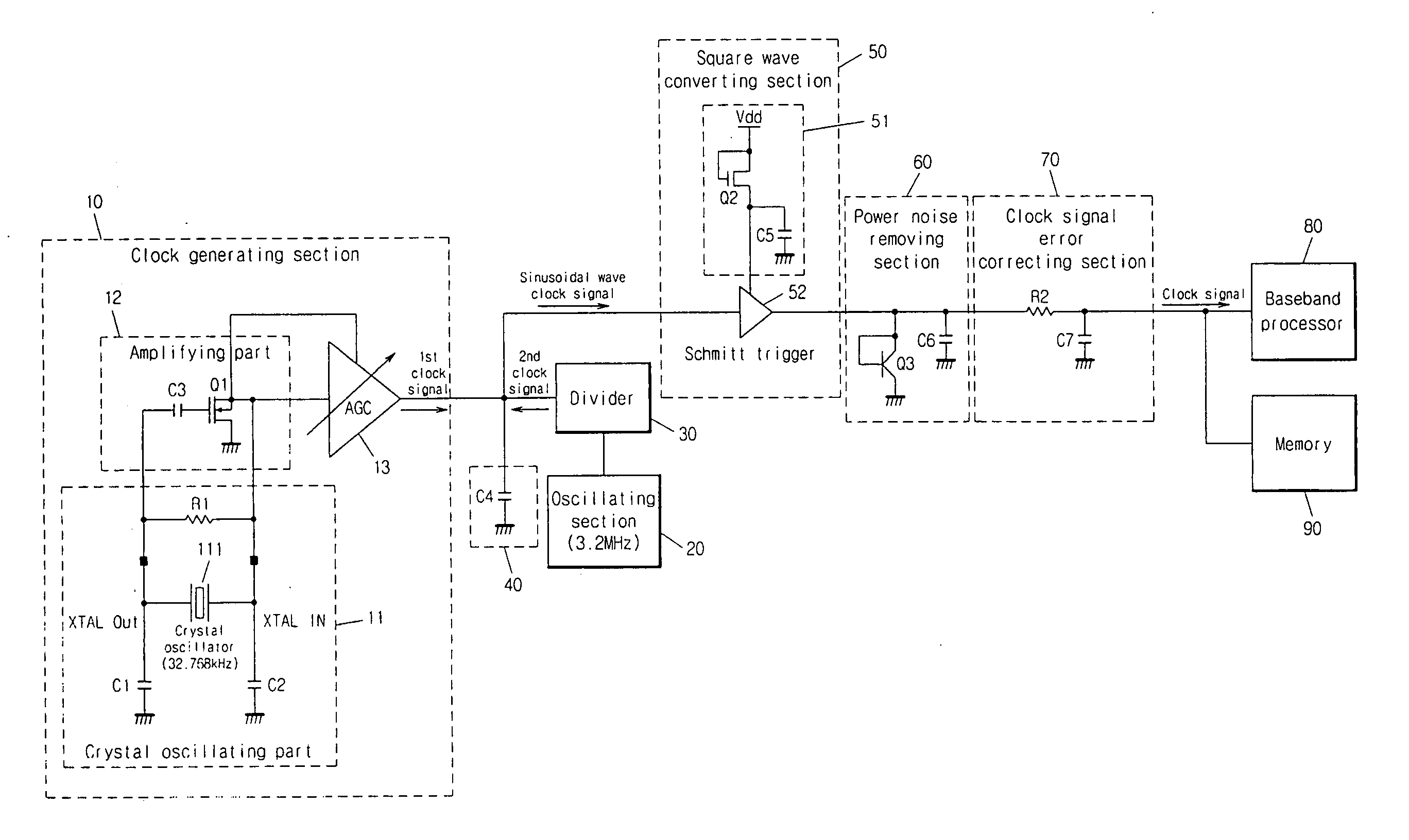
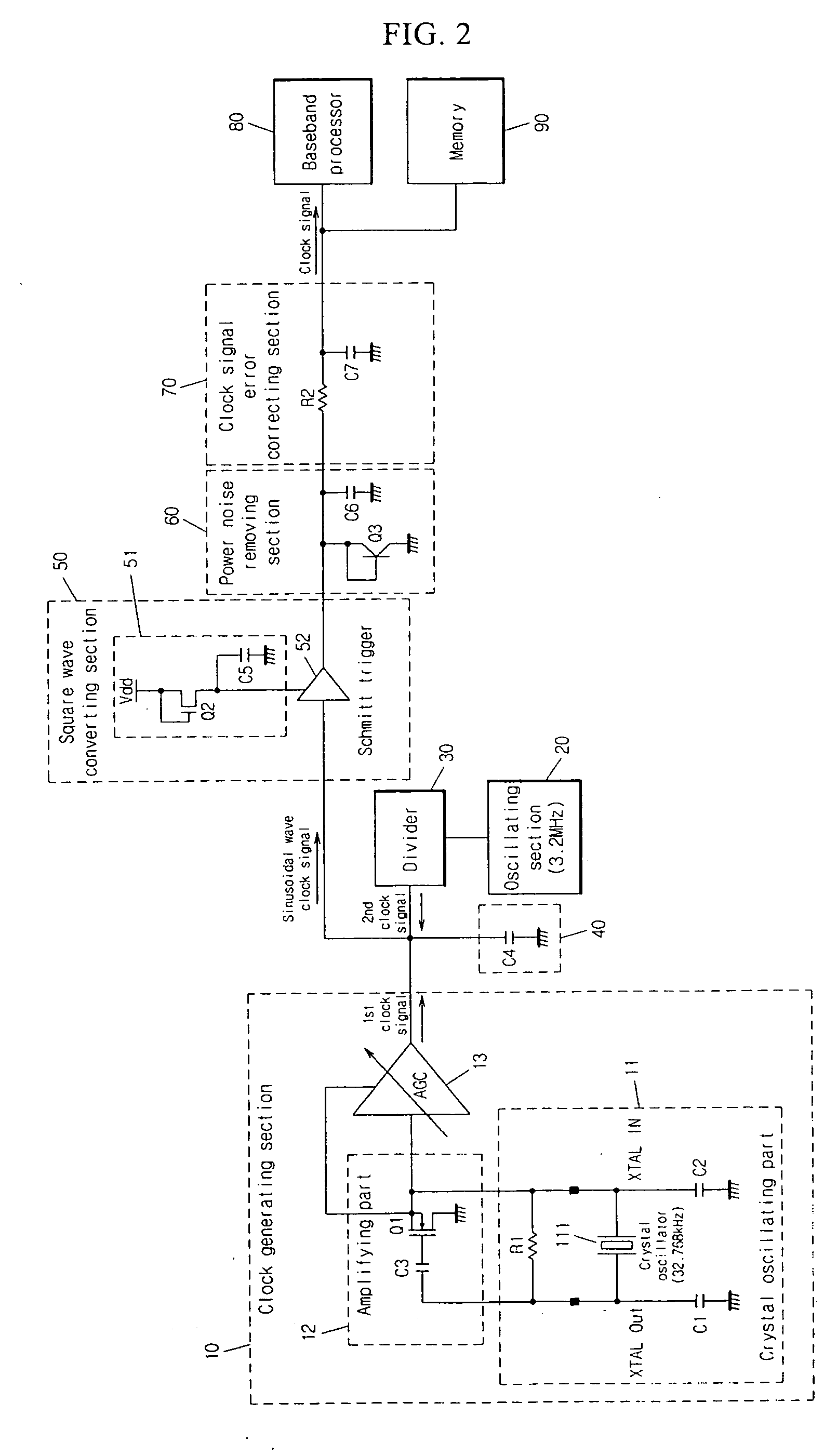
[0019] An apparatus for generating a clock signal in a mobile communication terminal according to an embodiment of the invention comprises a clock signal generating section 10, an oscillating section 20, a divider 30, a surge current preventing section 40, a square wave converting section 50, a power noise removing section 60 and a clock signal error correcting section 70.

[0020] The clock signal generating section 10 outputs a first sinusoidal wave clock signal. The clock signal generating section 10 may comprise a crystal oscillating part 11, an amplifying part 12 and an automatic gain control (AGC) 13.

[0021] The crystal oscil...


PUM


Abstract

Disclosed is an apparatus for generating a stable clock signal having a Long term jitter noise removed therefrom. In a mobile communication terminal having a power management chip for converting a sinusoidal wave oscillated in a crystal into a clock signal of square wave, the sinusoidal wave is converted into a square wave clock signal by the stabilized driving power having no alternating current components, and thus a power noise of the square wave clock signal is removed. Then, the square wave clock signal having the power noise removed therefrom is outputted after a predetermined delay time. Accordingly, it is possible to supply the clock signal having the Long term jitter noise removed therefrom and synchronized to each device in the mobile communication terminal.

Description

CROSS-REFERENCE TO RELATED APPLICATION [0001] The present application is claiming priority of Korean Patent Application No. 10-2005-0000913, filed on Jan. 5, 2005, the content of which is herein incorporated by reference. BACKGROUND OF THE INVENTION [0002] 1. Field of the Invention [0003] The present invention relates to an apparatus for generating and supplying clock signal having a Long term jitter noise removed therefrom to each device in a mobile communication terminal containing the apparatus and having a power management chip mounted thereto for converting a sinusoidal wave oscillated in a crystal to generate a clock signal of square wave. [0004] 2. Description of the Prior Art [0005] A jitter noise occurring in a wireless circuit is meant by a kind of distortion phenomenon that an output signal vibrates for a time axis. Due to the jitter noise, an output signal in a time area is outputted after a predetermined delay time. In addition, a waveform of the output signal in a freq...

Claims


Application Information

Patent Timeline
IPC IPC(8): H04J3/06
CPCG06F1/04G06F1/10H03K5/08H03K5/1565F16B15/06F16B15/0015F16B15/08
Inventor PARK, BOOK SUNG
Owner PANTECH CORP
Why Eureka
Try Eureka