
Flexible compression unit for on demand, portable, collapsible fluid delivery systems

a fluid delivery system and flexible technology, applied in the direction of liquid transfer devices, transportation and packaging, cooking vessel lids/covers, etc., can solve the problems of not providing a flexible means of applying pressure to a collapsible container, and the use of this proposed device generally requires a considerable amount of suction, etc., to achieve the effect of sufficient length

Inactive Publication Date: 2006-07-06
REICHERT LUCAS +1
View PDF2 Cites 16 Cited by
  • Summary
  • Abstract
  • Description
  • Claims
  • Application Information

AI Technical Summary

Benefits of technology

[0009] The system preferably further includes a means of variably pressurizing the pliable compression chamber with oxygen or ambient air. Air or oxygen can be introduced into the flexible pressure vessel through a length of tubing permanently attached to the pressure chamber at one end and having appropriate connectivity at the other end. The tubing is of sufficient length to extend out of the flexible backpack that carries the collapsible fluid vessel, making the connection end thereof readily accessible to the user.
[0011] After inflation of the pressure chamber using a cylinder of compressed oxygen, a stopcock, or other valve mechanism attached to the connection end of the tube can be closed to prevent oxygen from escaping the flexible pressure chamber upon disconnection of the oxygen cylinder. The stopcock can be opened, releasing the pressure, should deflation be desired.

Problems solved by technology

Use of this proposed device generally requires a considerable amount of suction to provide adequate flow of fluid to the user.
Although one of these mechanisms provides for a collapsible fluid container, and others provide for pressurization of rigid vessels, which also contain the liquid to be dispensed, they do not provide a flexible means of applying pressure to a collapsible container.

Method used


Image

  • Flexible compression unit for on demand, portable, collapsible fluid delivery systems
  • Flexible compression unit for on demand, portable, collapsible fluid delivery systems
  • Flexible compression unit for on demand, portable, collapsible fluid delivery systems

Examples


Embodiment Construction

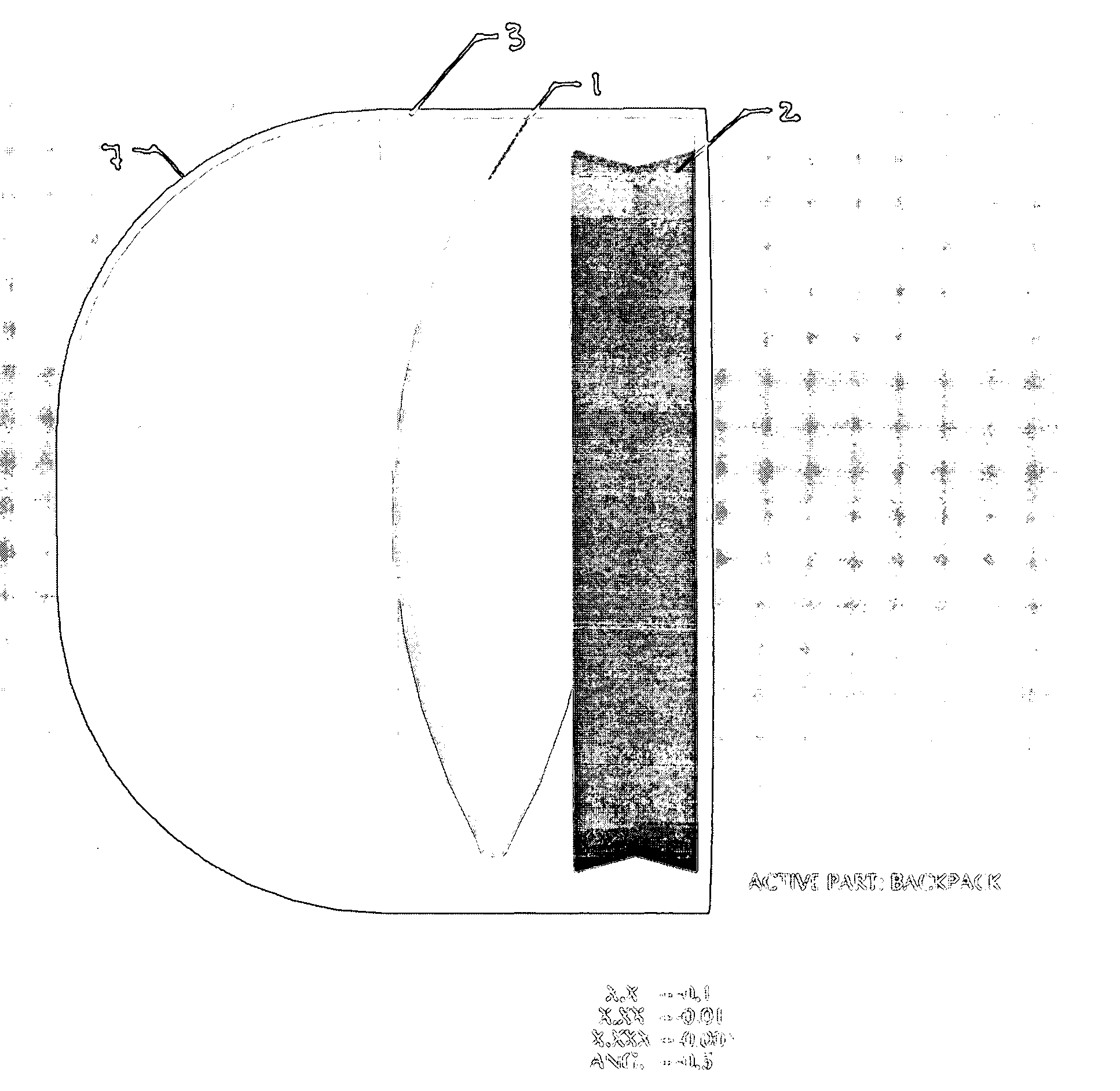
[0017] Broadly this invention provides system of applying pressure to a collapsible container of water stored within a flexible backpack as depicted in FIG. 3. The pressure application system consists of an inflatable bladderl, which can be positioned next to collapsible fluid container 2, held with flexible backpack 3.

[0018] The system is further comprised of tube 4 of sufficient length to extend beyond the confines of backpack 3 so as to be able to extend all the way to the mouth when the backpack is in position on a person's back.

[0019] The preferred embodiment of the system provides means of pressurizing the inflatable bladder by means of an inflation ball 5 attached to the distal end of the tube 4 by means of stopcock connector 6. The pressurization ball can be readily disconnected from tube 4 for ease of assembly of within the backpack. The stopcock 6 may be rotated to the closed position to prevent air escaping from the inflated bladder 1, if the pressurization ball 5 is re...


PUM


Abstract

A system which applies pressure to a flexible, collapsible container of liquid stored within a flexible backpack. The system has an inflatable bladder of similar size and shape as the collapsible container of water upon which pressure is to be exerted. A tube of permanently attached to the inflatable bladder through which air or other gas may pass providing means to inflate the bladder. The tube being of sufficient length to extend beyond the confines of the backpack containing the liquid chamber extending to with easy reach of the person wearing the backpack. A stopcock or other valve connection providing means to control airflow into and out of the inflatable bladder. A pressure ball which provides means of forcing air into the bladder by repeated hand pressure on the ball.

Description

STATEMENT REGARDING FEDERALLY SPONSORED RESEARCH OR DEVELOPMENT [0001] Not Applicable BACKGROUND OF INVENTION [0002] Collapsible fluid delivery systems exist for use by hikers, runners, and bicyclists, where constant hydration of the body is extremely important. These hydration delivery systems consist of a collapsible fluid container held within a flexible back pack that is removable secured between the shoulders of the user. A mouthpiece, configured to be held in the mouth of the user, is connected to the container by a length of flexible tubing. The mouthpiece is comprised of a valve device within a chamber that normally prevents flow of liquid. When compressed by the teeth, the spring-biased valve within the mouthpiece chamber opens, allowing flow of liquid from the container into the mouth. [0003] U.S. Pat. No. 5,060,833 addresses the concept of a collapsible water container within a flexible backpack. This proposal includes the valve within a mouthpiece attached to the contain...

Claims


Application Information

Patent Timeline
IPC IPC(8): A47J36/08B67D5/64A45F3/16B67D7/84
CPCA45F3/04A45F3/20A45F2003/166
Inventor REICHERT, LUCASREICHERT, GABRIEL
Owner REICHERT LUCAS
Learn More