
Optical disk device and optical component used therein

a technology of optical components and optical disks, applied in the direction of data recording, disposition/mounting of heads, instruments, etc., can solve the problems of increasing the size of the device, increasing the cost due to the increase of the number of parts, and contributing to the cost increase. , to achieve the effect of reducing the size and cost of the devi

Inactive Publication Date: 2006-06-29
CANON KK
View PDF4 Cites 13 Cited by
  • Summary
  • Abstract
  • Description
  • Claims
  • Application Information

AI Technical Summary

Benefits of technology

[0058] It is, therefore, an object of the present invention to provide an optical disk device and an optical component used in the device that can realize size and cost reduction of the device.

Problems solved by technology

In a case where a short wavelength light source and an objective lens of a high NA are used, there remain the following basic problems.
(1) Being susceptible to tilt of disk (2) Being susceptible to thickness error of transparent substrate (3) Being susceptible to wavelength hop of light source
However, when the above described position detecting sensor as position detecting means is used, there are posed the problems such as device size increase for providing disposition space thereof and cost increase due to increase of the number of parts.
Further, as also disclosed in Japanese Patent Application Laid-Open No. 2003-131113, in order to determine a reference position, it is firstly necessary to adjust an original position of a photosensor at a manufacturing factory, which contributes to cost increase.
This is because it is easy to determine the position in accordance with a part position, such as abutment through striking of a detected part against a detection means or the like and further because detection through contact makes it difficult to be affected by a temperature change.
However, there will be an amount of overrun that the optical pick-up will make before the reference position is detected, at an end portion of the movable range, which contributes to increase of the device size.
Further, in the case of the position detecting sensor of contact-type, there is mentioned the problem of shock (or impact) and vibration at the time of contact.

Method used


Image

  • Optical disk device and optical component used therein
  • Optical disk device and optical component used therein
  • Optical disk device and optical component used therein

Examples


first embodiment

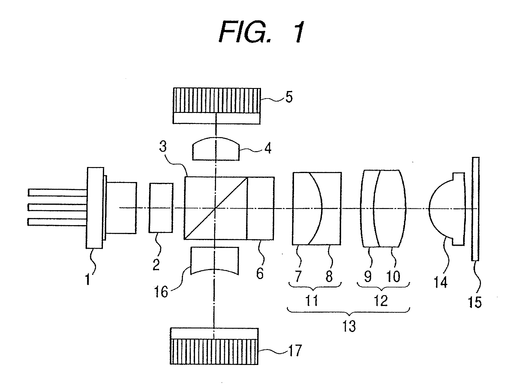
[0086] A first embodiment of the present invention will be shown below. The first embodiment shows a case where the present invention is applied to a spherical aberration correcting mechanism of an optical pick-up.

[0087]FIG. 1 is a schematic diagram of an optical system of an optical pick-up device in accordance with the present embodiment.

[0088] A beam emitted from a semiconductor laser 1 is split into a main beam and two subbeams by a diffraction grating 2.

[0089] The subbeams are used for generation of a servo signal for DPP (differential push-pull) detection.

[0090] The beams from the diffraction grating are partially reflected by a PBS 3 and converged into a monitor PD 5 by a condenser lens 4.

[0091] An output of the monitor PD is used for controlling the emission power of the semiconductor laser 1.

[0092] The beams transmitted through the PBS 3 is made parallel light flux by a collimator lens 13 as a lens unit through a λ / 4 plate 6, and forms an image on an information recor...

second embodiment

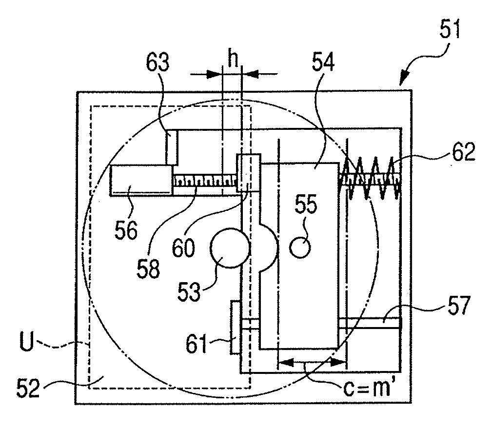
[0151] A second embodiment of the present invention will be described below. The second embodiment shows a case where the present invention is applied to an optical pick-up moving mechanism of an optical disk device.

[0152]FIGS. 9A, 9B, and 9C are schematic views each showing an optical disk device, and FIG. 9A shows the present embodiment, FIG. 9B shows a conventional example in which a position detecting sensor 59 to be described later is provided on a disk inner periphery side, and FIG. 9C shows a conventional example in which a position detecting sensor 59 is provided on a disk outer periphery side.

[0153] The basic structure of the present optical disk device is the same as the prior art example shown in FIG. 14, and like numerals denote like parts.

[0154] In FIGS. 9A, 9B, and 9C, a two-dot chain line shows a disk-shaped recording medium in which an information is recorded / reproduced.

[0155] Further, reference numeral 60 denotes a nut member which is a drive member, reference n...


PUM

PropertyMeasurementUnit
thicknessaaaaaaaaaa
focal lengthaaaaaaaaaa

Abstract

An optical disk device is provided which can realize size and cost reduction and which includes: an optical pick-up; a drive source; a drive member for moving the optical pick-up by utilization of a drive force generated by the drive source; and a striking member for striking against the drive member, wherein abutment between the striking member and the drive member results in loss of synchronism of the drive source and a predetermined position of the drive member is determined. An optical component for use in the optical disk device is also provided.

Description

BACKGROUND OF THE INVENTION [0001] 1. Field of the Invention [0002] The present invention relates to an optical disk device using, for example, CD, DVD, MD, or Blu-ray Disc, and an optical component used in such a device. [0003] 2. Related Background Art [0004] In recent years, in the field of an optical disk device, in order to attain a higher density, study of technology for decrease of wavelength of a light source and for increase of NA of an objective lens has been extensively conducted. [0005] Further, in some fields, a device using a 405 nm semiconductor laser and an objective lens of NA=0.85 has begun to be commercially manufactured. [0006] In a case where a short wavelength light source and an objective lens of a high NA are used, there remain the following basic problems. [0007] (1) Being susceptible to tilt of disk [0008] (2) Being susceptible to thickness error of transparent substrate [0009] (3) Being susceptible to wavelength hop of light source [0010] Of the above prob...

Claims


Application Information

Patent Timeline
Patent Type & Authority Applications(United States)
IPC IPC(8): G11B7/085G11B7/08G11B7/09
CPCG11B7/085G11B7/08582G11B7/08588G11B7/0948G11B7/1376G11B7/13927G11B2007/13727
Inventor TORII, SHINNOSUKE
Owner CANON KK
Learn More