
Surgical fasteners and related implant devices having bioabsorbable components

a bioabsorbable, fastener technology, applied in the field of surgical fasteners, can solve the problems of insufficient strength of bioabsorbable substances to withstand the stresses encountered, re-operation is usually required, and more extensive and prolonged surgery may be required, so as to achieve sufficient flexibility, generate or stimulate bone growth, and the effect of sufficient strength

Inactive Publication Date: 2006-06-29
BIODYNAMICS
View PDF17 Cites 1274 Cited by
  • Summary
  • Abstract
  • Description
  • Claims
  • Application Information

AI Technical Summary

Benefits of technology

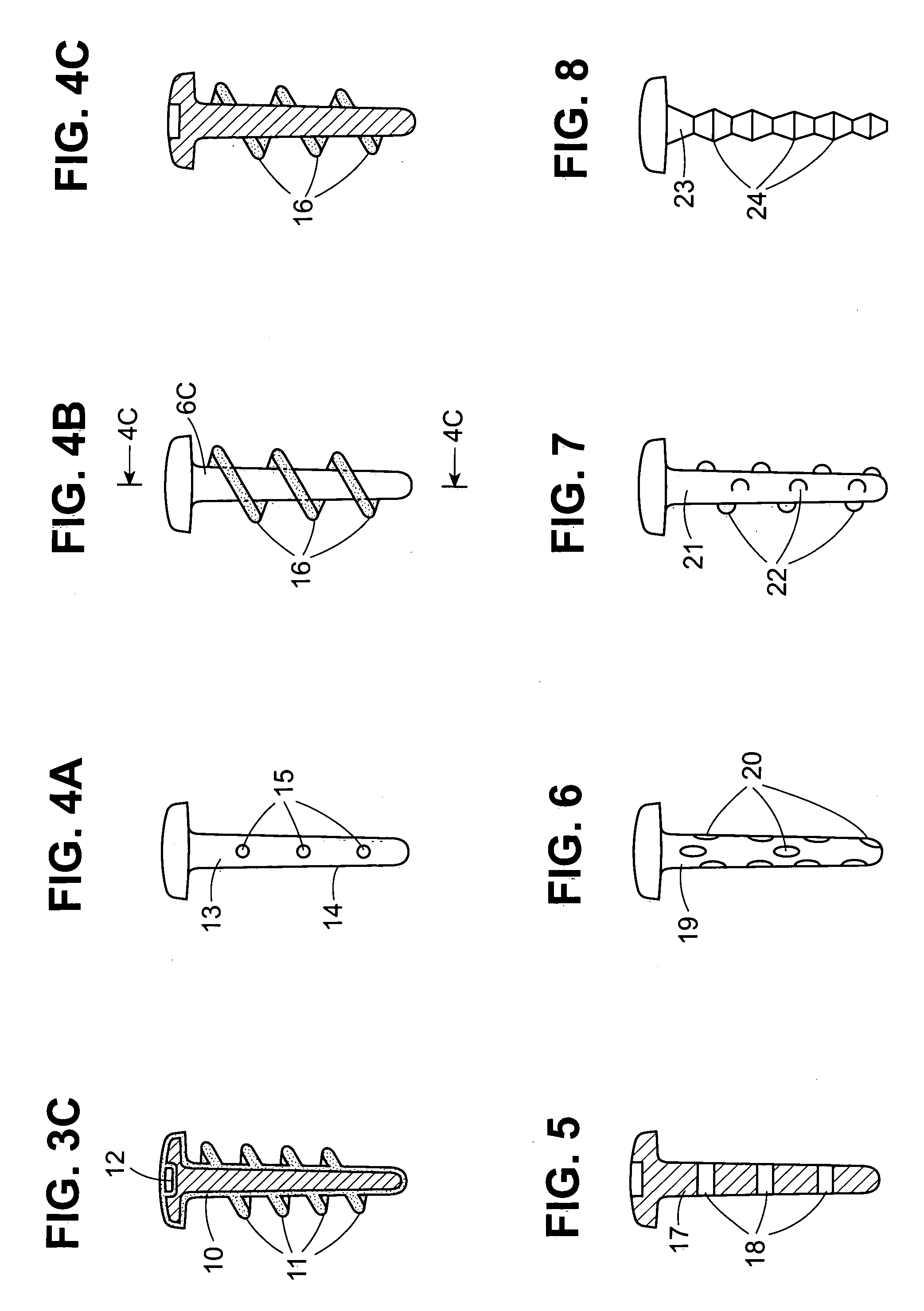
[0010] The base is made with attachment elements which provide for the mechanical attachment of the bioabsorbable material thereto. This can include, for example, indentations, protrusions, corrugations, partial or through holes, slits, nubs, pockets, bumps, splines, knurls; mechanical roughening such as by sanding, sand blasting, bead blasting, shot peening, tumbling or etching; coating or plating with an adherency enhancing alloy or other composition or the like. Combinations of two or more of such attachment elements can also be employed. Alternatively, the base can be made from a mesh material or cable which provides for attachment of the bioabsorbable material by means of the structure of the mesh or cable. The objective in selecting a material for the base, in addition to biocompatibility, is to find a material having sufficient strength for the particular application but also, in many cases, sufficient flexibility when implanted in the body. For example, a screw that is sufficiently flexible to allow micro-motion will be less likely to back out, will absorb shock and may generate or stimulate bone growth.

Problems solved by technology

However, for fastening applications and other applications which require strong materials, bioabsorbable substances usually do not have sufficient strength to withstand the stresses encountered during surgery and, following surgery, in the body.
When such materials fail during surgery, more extensive and prolonged surgery may be required.
And when such materials fail in the body, re-surgery is usually required.

Method used


Image

  • Surgical fasteners and related implant devices having bioabsorbable components
  • Surgical fasteners and related implant devices having bioabsorbable components
  • Surgical fasteners and related implant devices having bioabsorbable components

Examples


Embodiment Construction

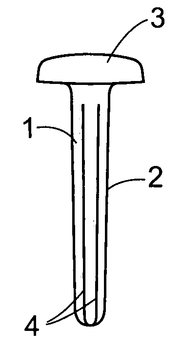
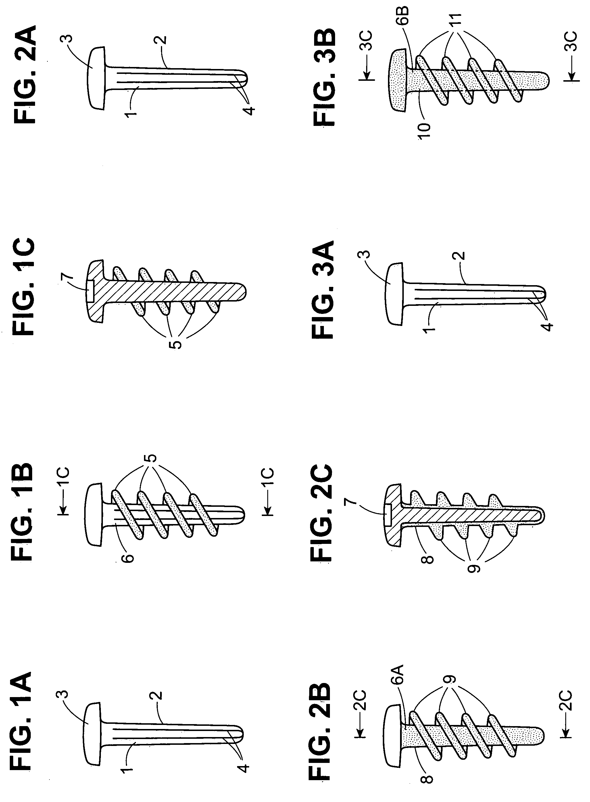
[0031]FIG. 1A illustrates a base 1 having a shank 2 and a head 3. The shank 2 contains grooves 4 which serve as attachment elements. In FIG. 1B bioabsorbable threads 5 have been attached to the base to make screw 6. FIG. 1C is a section view of screw 6 taken along section line a-a of FIG. 1B. Slot 7 is illustrated in the head. Following implantation of screw 6 and the eventual absorption by the body of threads 5, the base 1 can optionally be removed smoothly from the body. In the prior art, when non-bioabsorbable screws are used, the threads may stick to the surrounding tissue and in such cases removal of the screws can cause injury to the patient. This problem is avoided when the screws of the present invention are used.

[0032]FIG. 2A illustrates the same base as illustrated in FIG. 1A. In FIG. 2B a bioabsorbable coating 8 with bioabsorbable threads 9 have been coated over and attached to the shank of the base to make screw 6A. This embodiment is illustrated further in FIG. 2C whic...


PUM


Abstract

Surgical implants including fasteners and related devices which are partially bioabsorbable. The implants are constructed of a non-bioabsorbable base comprising metals and or high strength plastic materials. The base is partially or completely coated with a bioabsorbable material which can have its own mechanical features, such as the threads on a screw. Attachment elements are provided on the base to enhance the mechanical attachment of the bioabsorbable material to the base. The implants can withstand the torques and stresses encountered during surgery and, following implantation, in the body.

Description

BACKGROUND OF THE INVENTION [0001] 1. Field of the Invention [0002] The present invention has to do with surgical fasteners and related devices which are implanted in the body. In particular, the invention has to do with improved surgical implants which are made with a base comprising metals and / or high strength plastic materials. Bioabsorbable materials are molded or otherwise applied onto the base and attached thereto. The base is made with elements which enhance the mechanical attachment of the bioabsorbable material to the base. The products of the invention can accordingly withstand the torques and stresses encountered during surgery and following surgery, in the body, while providing the benefits of bioabsorbability to the patient. [0003] 2. The Related Art [0004] Bioabsorbable surgical fastening devices such as screws, pins, tacks, bolts, nails, suture anchors, staples, etc. and related devices such as rods, plates, wires and the like are now available for use in surgery. Suc...

Claims


Application Information

Patent Timeline
IPC IPC(8): A61B17/58
CPCA61B17/0642A61B17/68A61B17/72A61B17/7266A61B17/82A61B17/8605A61B17/8625A61B17/864A61B17/866A61B2017/00004A61B2017/0647A61B2017/0648A61F2002/30064
Inventor RALPH, JAMES D.TATAR, STEPHEN L.TROXELL, THOMAS N.
Owner BIODYNAMICS
Learn More