Colorimetric device and colour determination process

a colorimetric device and colour determination technology, applied in the field of colorimetric devices and colour determination processes, can solve the problems of increasing cost and reducing ruggedness, not addressing the problem of specular reflection affecting colour determination, and people who are colourblind have difficulty in choosing clothes from their wardrobes

Inactive Publication Date: 2006-06-29
BRYTECH
View PDF19 Cites 34 Cited by
  • Summary
  • Abstract
  • Description
  • Claims
  • Application Information

AI Technical Summary

Benefits of technology

[0038] Preferably, the first, second and third light sources in each set are packaged as a single semiconductor device, such as a so-called tri-colour LED, The corresponding light sources in each set, i.e., emitting light having substantially the same wavelength, may be energized simultaneously, conveniently by using the same drive signal to operate all of the light sources. Alternatively, the corresponding light sources in each set may be energized in quick succession and the successive measurements combined.

Problems solved by technology

People who are blind or colour-blind have difficulties when choosing their clothes from their wardrobes.
A disadvantage of these devices, however, is that they require the use of optical components, such as optical filters, light pipes / guides, lenses, mirrors, and reflector cones, between the light source(s) and detector(s), which increases cost and reduces ruggedness.
A further disadvantage of the foregoing devices, except that disclosed by Wagner et al. and the three disclosed by Walowit et al., is that they do not address the problem of specular reflection affecting colour determination.
If specularly reflected components of the reflected light are collected for measurement, they will usually result in errors in the diffuse colour determination of the surface.
While materials such as cloth and fabric generally have low levels of specular reflectivity and the measurement of their colours would not be greatly affected by including the specular components, measurements of more glossy surfaces characteristic of leather or vinyl for shoes or jackets would be severely affected.
While the above described known colorimeters may work satisfactorily on isotropic flat surfaces, such as coloured paper, they are not necessarily entirely satisfactory for determining the colour of non-isotropic textured surfaces, such as fabrics which have different luminous reflectivity depending upon the orientations of the illumination and viewing axes relative to the nap of the pile, or, where the fabric is woven, the direction of the fibres.
Moreover, measurement accuracy also may be impaired if the material is a fabric that has different colours of thread extending in different directions, for example warp and weft of different colours, giving a different average color reading from different directions.
A further limitation of some of the above-mentioned devices concerns the colour determination process.
However, there are issues of complexity, cost and robustness associated with graded circular filters and the associated rotating mechanisms.
Thus, the provision of physical filters replicating the CIE spectral functions is not entirely practical and, even to the limited extent that it might be practical, would be expensive.
The main cost of this approach is the provision of the optical system that typically includes beam-splitters as well as filters.
Disadvantageously, using multiple light sources and detectors increases complexity and cost.
Another disadvantage, identified in the discussion of prior art in U.S. Pat. No. 5,838,451 (McCarthy), was the lack of availability of light sources with peak wavelengths in the region around 550 nm.
This is still not entirely satisfactory since LEDs that are readily available and inexpensive do not necessarily have the required wavelength distributions or values.
While this is particularly suitable for use where the possible colours of the surfaces are known a priori, as might be the case when sorting articles according to colour in a manufacturing environment, it has limitations if used for identifying a large number of colours that are not known specifically a priori.

Method used


Image

  • Colorimetric device and colour determination process
  • Colorimetric device and colour determination process
  • Colorimetric device and colour determination process

Examples


Embodiment Construction

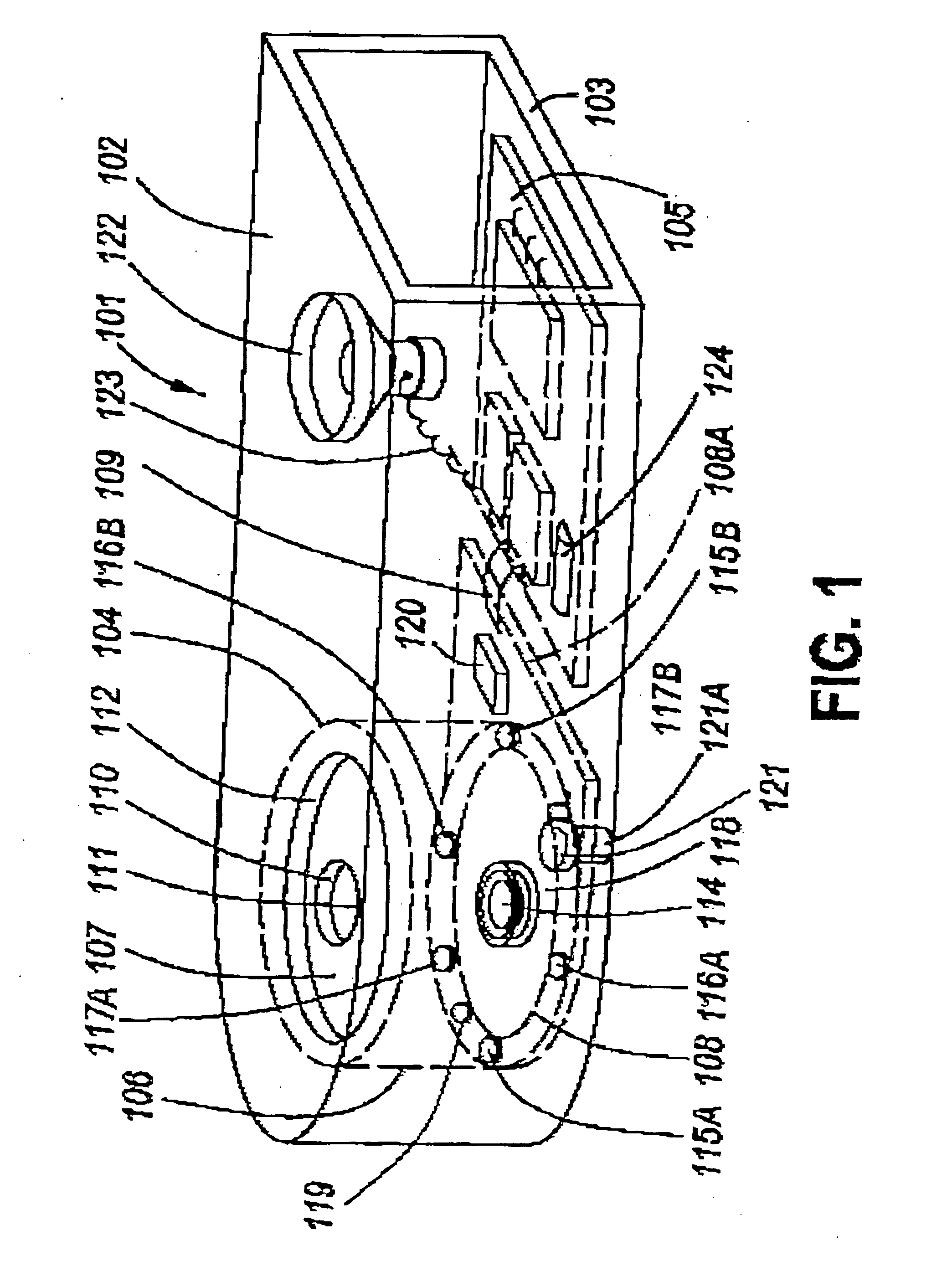
[0071]FIG. 1 is a perspective view of a colorimetric device, specifically a colorimeter 101 comprising a palm-sized casing 102, shown with one end removed, and a base 103. A sensor unit 104 is mounted upon the base 103 at one end and a printed circuit board (PCB) 105 is mounted upon the base 103 at its opposite end.

[0072] The sensor unit 102 comprises a cylindrical housing 106 closed at one end by an integral end wall 107 and at its opposite end by a second printed circuit board 108 which has a plinth portion 108A extending beyond the housing 106 towards the first printed circuit board 105, to which it is connected by a cable 109 The second printed circuit board 108 seals that end of the housing 106 and mounts the sensor unit 102 upon the base 103.

[0073] The length of the housing 106 is such that the end wall 107 abuts the inner surface of the casing 102. A central aperture 110 in the end wall 107 is sealed by a transparent window element 111. The casing 102 has a hole 112 which i...


PUM


Abstract

A hand-held colorimetric device (101) suitable for use by blind or colour-blind individuals to determine the colour of a surface-under-test (SUT), for example of a fabric, has an aperture (110) which, in use, is covered by the SUT (113) whose colour is to be determined. Six LEDs (115A, 115B, 116B, 117A and 117B) arranged in pairs (115A/115B, 116A/116 B, 117a/117B) emitting red/orange, green, and blue light illuminate the SUT and diffuse reflections therefrom containing red/orange, green, and blue spectrum sample values are used to determine the luminous reflectivity and chromaticity values for the colour of the SUT. The measured values are compared with colorimetric values of reference surfaces to determine the colour of the SUT. The colorimetric device may output the name of the colour aurally.

Description

CROSS-REFERENCE TO RELATED APPLICATIONS [0001] This application claims priority from U.S. Provisional patent application Ser. No. 60 / 638,345, filed Dec. 23, 2004 and U.S. Provisional patent application Ser. No., 60 / 648,703, filed Feb. 2, 2005, the contents of both of which are incorporated herein by reference.BACKGROUND OF THE INVENTION [0002] 1. FIELD OF THE INVENTION [0003] This invention relates to colorimetric devices, and a colour determination process for use therewith. The invention is applicable especially to colorimetric devices that identify the measured colour by name or by standardized coordinates. [0004] 2. DESCRIPTION OF THE PRIOR ART [0005] People who are blind or colour-blind have difficulties when choosing their clothes from their wardrobes. They would be greatly assisted by a device that would measure the colour of items such as socks, shoes, shirts, pants etc., and announce the results in an audible or other non-visual format. To meet the requirements of this mark...

Claims


Application Information

Patent Timeline
Patent Type & Authority Applications(United States)
IPC IPC(8): G01J3/50
CPCG01J3/02G01J3/0262G01J3/0264G01J3/0272G01J3/0283G01J3/0291G01J3/50G01J3/501G01J3/524G01J2001/4242
Inventor KAHN, DAVID ALEXANDERDAVEY, JOHN C.B.
Owner BRYTECH
Why Eureka
Try Eureka