
Display apparatus having temperature compensation function

a technology of temperature compensation and display apparatus, which is applied in the direction of static indicating devices, instruments, solid-state devices, etc., can solve the problems of voltage noise, large voltage noise, and voltage noise, so as to avoid a rapid change in drive condition, reliable temperature data, and power consumption of temperature measuremen

Inactive Publication Date: 2006-06-29
ROHM CO LTD
View PDF6 Cites 11 Cited by
  • Summary
  • Abstract
  • Description
  • Claims
  • Application Information

AI Technical Summary

Benefits of technology

This solution allows for precise temperature compensation with negligible measurement error, reducing power consumption and avoiding abrupt changes in display brightness, while maintaining the operation of the step-up circuit without increasing costs or dimensions.

Problems solved by technology

When the step-up circuit is stepping up a power source voltage towards a required step-up voltage through switching operation of switches (then the circuit is referred to as being in active state), it is likely that the switching operation generates a voltage noise on, for example, power supply lines, ground lines, and signal lines involved.
Voltage noise also appears very often when a large drive current is passed to a display panel (that is, when the drive current changes rapidly).
The voltage noise becomes large especially when a display apparatus has a step-up circuit, a temperature sensor, and a drive circuit all formed on the same semiconductor substrate.
Since voltage noise becomes a source of error in the temperature measurement, accurate temperature compensation of the operating conditions cannot be attained in such display apparatus.
However, it is not a realistic solution, since it causes an increase of cost and increases the dimensions of the display.

Method used


Image

  • Display apparatus having temperature compensation function
  • Display apparatus having temperature compensation function
  • Display apparatus having temperature compensation function

Examples


Embodiment Construction

[0050] Preferred embodiments of a display apparatus of the invention will now be described with reference to the accompanying drawings.

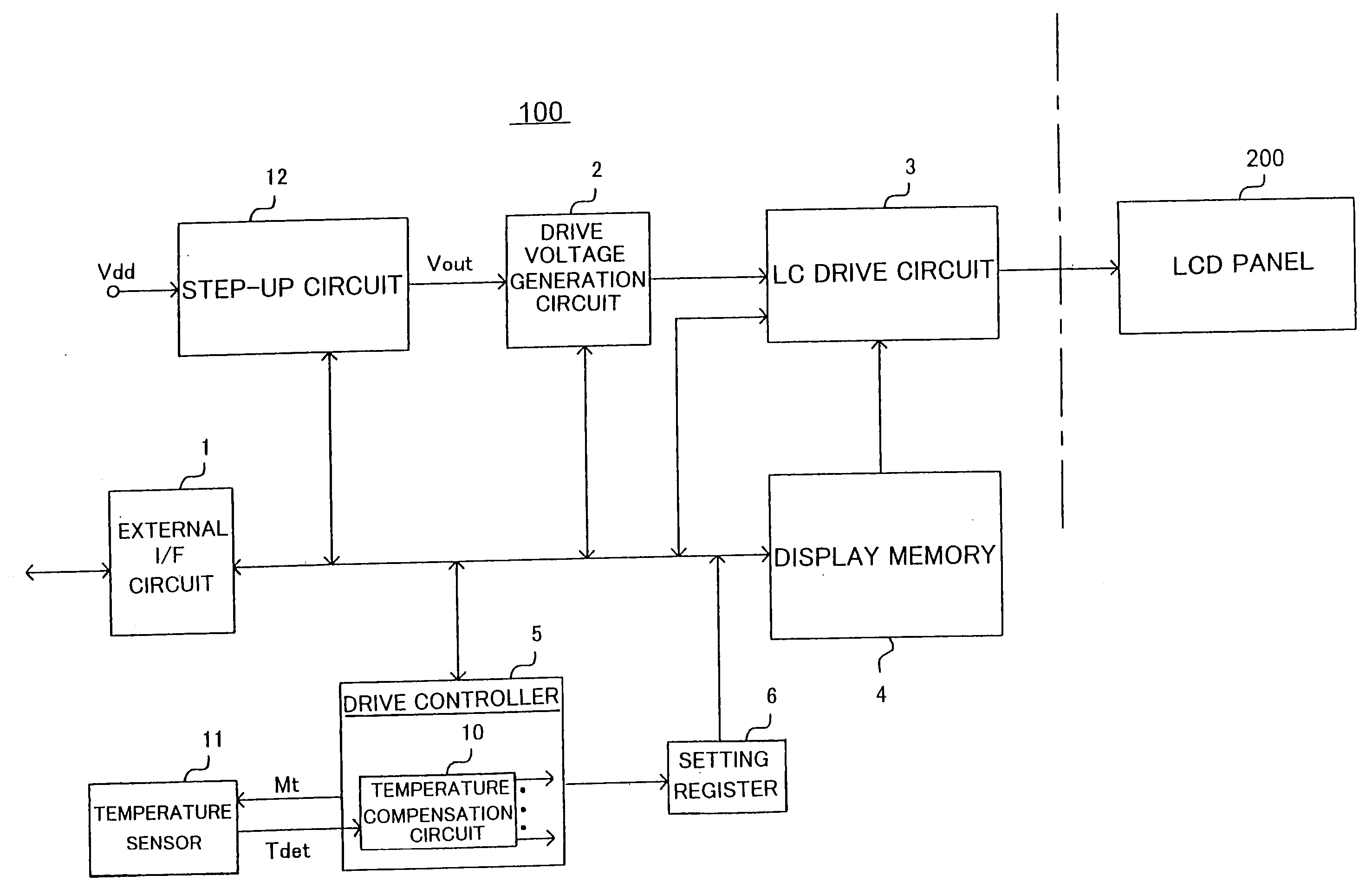
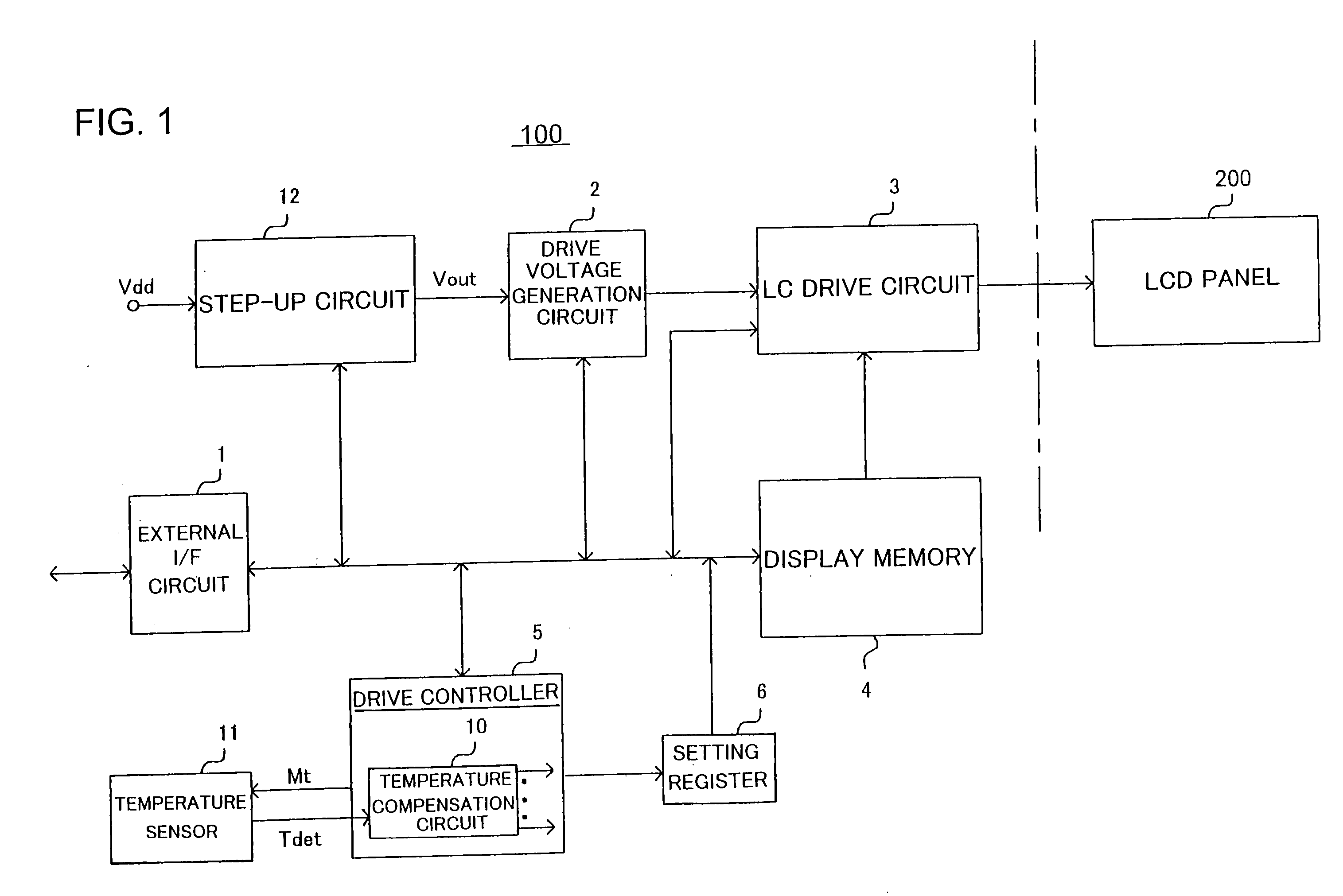
[0051] Referring to FIG. 1, there is shown a drive 100 for driving an LCD display panel 200 of an LCD apparatus according to the invention. The drive will be referred to as LCD drive. The LCD drive 100 has a modular structure in which different modules or components are formed on the same semiconductor device. The LCD drive 100 includes such major components as an external I / F circuit 1, a drive voltage generating circuit 2 constituting a drive circuit together with an LCD drive circuit 3, a display memory 4 comprising a RAM for example, a drive controller 5, a setting register 6, a temperature compensation circuit 10, a temperature sensor 11, and a step-up circuit 12. The temperature compensation circuit 10 is built in the drive controller 5 as shown in FIG. 1. The temperature compensation circuit 10 may be provided within the drive voltage generat...


PUM

PropertyMeasurementUnit
switching frequencyaaaaaaaaaa
voltage Vddaaaaaaaaaa

Abstract

The invention provides a display apparatus having a temperature sensor and a step-up circuit generating a drive voltage of the display apparatus by stepping up a power source voltage. The temperature sensor provides temperature data indicative of the temperature of the display panel with a reduced measurement error without limiting the operation of the step-up circuit. To do so, in view of the fact that the step-up circuit has alternating active state in which the circuit is stepping up a source voltage to output a required step-up voltage and inactive state in which no stepping operation is made, the temperature sensor is adapted to obtain temperature data while the step-up circuit is inactive. The temperature data obtained is supplied to a temperature compensation means for changing the drive condition setting value that define the drive condition of the display panel to compensate for the temperature change.

Description

FIELD OF THE INVENTION [0001] The invention relates to a display apparatus utilizing, for example, liquid crystal display (LCD) and organic electroluminescent display (ELD). BACKGROUND OF THE INVENTION [0002] Display apparatuses utilizing LCD and ELD have a step-up circuit for stepping up a given power source voltage to a drive voltage for driving the display. Expressive power of such display means have been increasingly improved in recent years. For example, display apparatuses of compact communications apparatuses such as PDAs and cellular phones have a high-resolution, varied gradation ability (ranging from monochrome to multi-color gradation), multi-color capability (ranging from monochrome to full colors). To drive LCD and ELD elements in a multi-color mode, it is necessary to drive them under an optimum driving condition. For this reason, it is necessary for a display apparatus to have means for accurately following the temperature dependent threshold voltage and the response ...

Claims


Application Information

Patent Timeline
Patent Type & Authority Applications(United States)
IPC IPC(8): G09G3/36G09G3/20G02F1/133G09G5/00H01L51/50H02M3/07
CPCG09G3/3696G09G2320/041H02M3/073H02M2001/0025H02M1/0025
Inventor NAIKI, TAKASHITAGUCHI, HARUO
Owner ROHM CO LTD
Learn More