
Systems and methods for detecting charge switching element failure in a battery system

a technology of charge switching element and battery system, which is applied in the field of battery system detection, can solve problems such as false charging current indications, and achieve the effect of eliminating the potential for disabling the battery system and being immune to nois

Active Publication Date: 2006-06-29
DELL PROD LP
View PDF39 Cites 33 Cited by
  • Summary
  • Abstract
  • Description
  • Claims
  • Application Information

AI Technical Summary

Benefits of technology

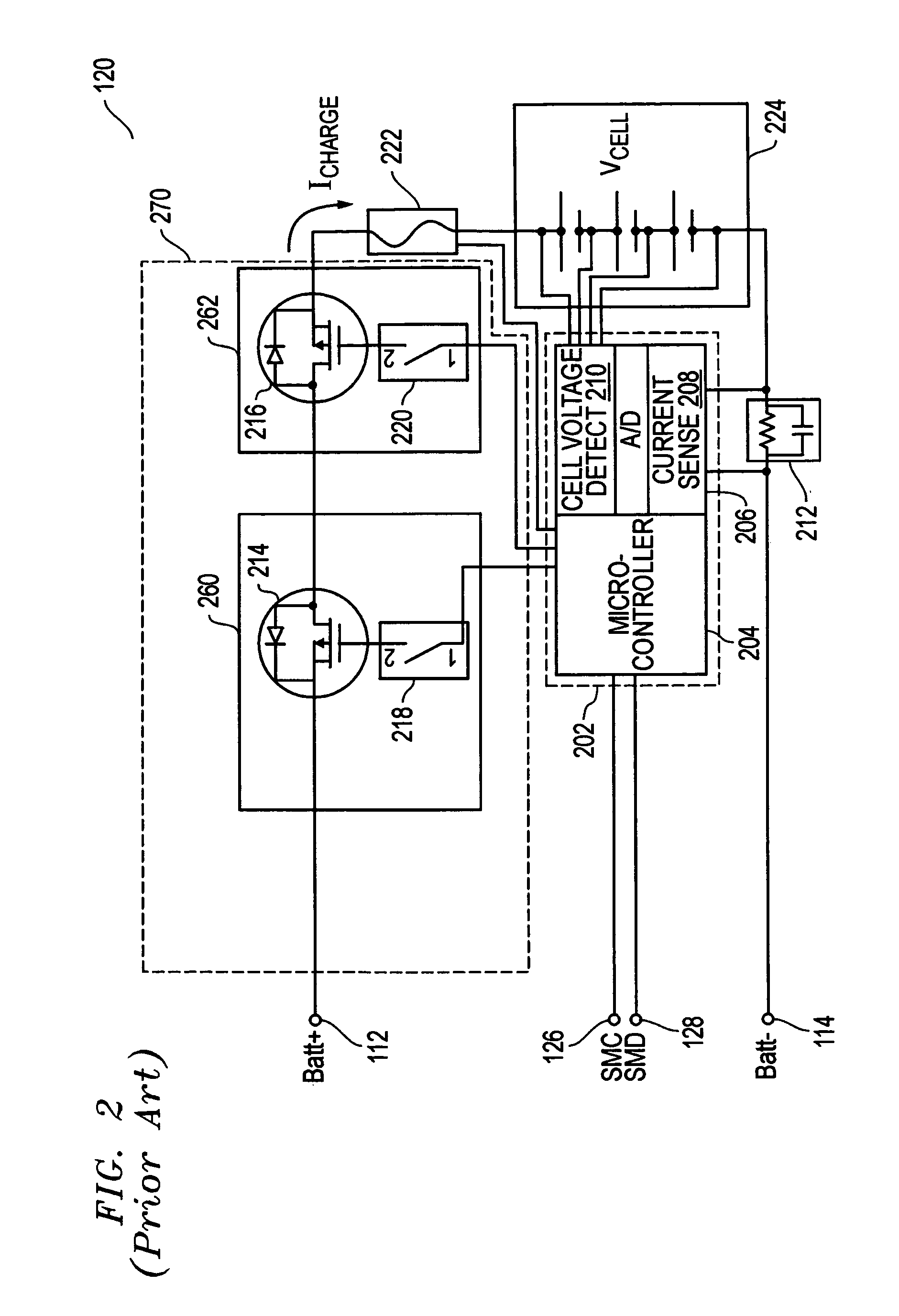
[0012] In one embodiment, the microcontroller of a battery system may be advantageously configured to combine measured battery circuit current with measured battery cell voltage information to detect charge switching element failure in a way that substantially eliminates the potential for disabling the battery system due to a false charging current indication, and without making it more difficult to detect an actual charge switching element failure. For example, the disclosed systems and methods may be implemented in one exemplary embodiment using the cell voltage analog to digital (“A / D”) port of an AFE that operates at a voltage level of about 2 to 3 volts and that is relatively immune to noise. This is in comparison to the much lower operating voltage level (1 millivolts) of the current sense resistor A / D port of a conventional AFE that is easily influenced by external noise. Thus, the disclosed systems and methods may be implemented to detect charge switching element failure using cell voltage measurements that are much more reliable than current sense resistor measurements that are conventionally employed alone.

Problems solved by technology

This is in contrast to conventional battery packs that rely on current measurement as the primary indicator for charge FET failure, and which are therefore susceptible to false charging current indications.

Method used


Image

  • Systems and methods for detecting charge switching element failure in a battery system
  • Systems and methods for detecting charge switching element failure in a battery system
  • Systems and methods for detecting charge switching element failure in a battery system

Examples


Embodiment Construction

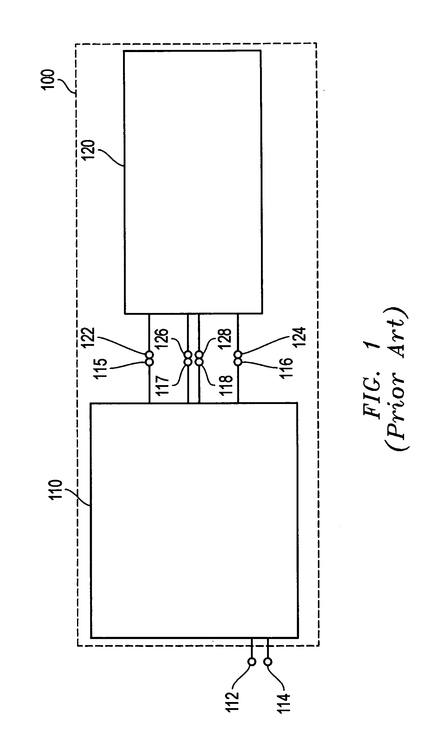
[0021]FIG. 3 shows a battery system 320 according to one embodiment of the disclosed systems and methods. Battery system 320 may be configured as a stand alone source of DC current, or may be provided as a permanent or replaceable component of a portable electronic device (e.g., battery pack of a portable information handling system such as a notebook computer). Besides notebook computers, other examples of such portable electronic devices include, but are not limited to, portable telephone devices (e.g., cellular phones, cordless phones, etc.), personal digital assistant (“PDA”) devices, MP3 players, cameras, computer peripherals, etc. In addition to portable electronic devices, it will be understood that the disclosed systems and methods may be implemented to power any other type of electronic device that is at least partially battery powered and that has electronic circuitry that is coupled to receive current from a battery system. In this regard, the disclosed systems and method...


PUM


Abstract

Systems and methods for detection of charge switching element failure (e.g., charge FET switching element) in a battery system, such as a battery system of an information handling system (e.g. notebook computer), in which an increase in cell voltage is employed as a criteria for detecting charge switching element failure.

Description

BACKGROUND OF THE INVENTION [0001] 1. Field of the Invention [0002] This invention relates generally to battery systems, and more particularly to detection of charge switching element failure in a battery system. [0003] 2. Description of the Related Art [0004] As the value and use of information continues to increase, individuals and businesses seek additional ways to process and store information. One option available to users is information handling systems. An information handling system generally processes, compiles, stores, and / or communicates information or data for business, personal, or other purposes thereby allowing users to take advantage of the value of the information. Because technology and information handling needs and requirements vary between different users or applications, information handling systems may also vary regarding what information is handled, how the information is handled, how much information is processed, stored, or communicated, and how quickly and...

Claims


Application Information

Patent Timeline
Patent Type & Authority Applications(United States)
IPC IPC(8): H02J7/00
CPCH02J7/0031H02J7/00308H02J7/00304
Inventor WANG, LIGONGMILLER, BRUCE A.STERZ, STEPHEN D.
Owner DELL PROD LP
Learn More