
Digital amplifier

a digital amplifier and amplifier technology, applied in the direction of amplifiers with semiconductor devices/discharge tubes, emergency protective circuit arrangements, emergency protective arrangements for limiting excess voltage/current, etc., can solve the problems of mosfet in the output stage being broken, and the inability to perform any time an operation to monitor load curren

Inactive Publication Date: 2006-06-22
YAMAHA CORP
View PDF6 Cites 8 Cited by
  • Summary
  • Abstract
  • Description
  • Claims
  • Application Information

AI Technical Summary

Benefits of technology

[0020] An object of the invention is therefore to provide a digital amplifier which can perform optimized protection operation.
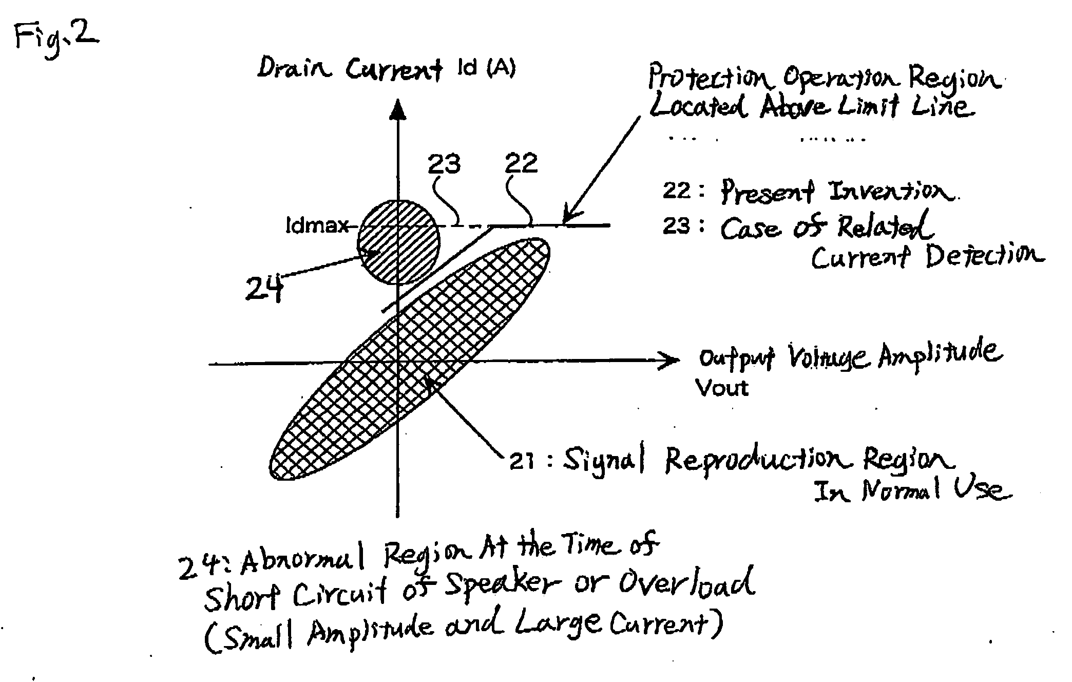
[0025] According to the digital amplifier of the invention, a PC limiter similar to that in the analog amplifier in the background art can be arranged. A speaker may be damaged in a short mode during reproduction with a small signal. A speaker with a low AC impedance beyond the real capability of the amplifier may be sounded with large amplitude. A speaker may be used for a long term with a part of speaker wires being left in contact with a negative terminal, a chassis, etc. due to customer's faulty wiring. In such a case, protection operation can be performed in response to a low current value. On the other hand, at the time of output with the maximum amplitude in a defined load, detection of abnormality can be suspended till the current of an output device reaches its rated current. It is therefore possible to obtain a safe and high-power amplifier.
[0027] Moreover, according to the digital amplifier according to the invention in which the amplitude of an input signal is controlled by the output of the protection unit, it is possible to automatically reduce a signal level to an amplitude level with which the output MOSFET can be driven in an amplitude range safe enough not to damage the output MOSFET, or it is possible to suppress only the maximum output amplitude. Particularly when a speaker with a low AC impedance beyond the real capability of the amplifier is sounded with large amplitude, reproduction can be performed continuously without shutting off the amplifier.

Problems solved by technology

As a result, the MOSFET in the output stage may be broken because protection operation is not carried out, for example, when a speaker is damaged in a short mode during reproduction with a small signal, when the speaker with a low AC impedance beyond the real capability of the amplifier is sounded with large amplitude, or when the speaker is used for a long term with a part of speaker wires being left in contact with a negative terminal, a chassis, etc. due to customer's faulty wiring.
Accordingly, there is a problem that the aforementioned PC limiter serving in the analog amplifier cannot detect the output amplitude of a final signal.
It is therefore impossible to perform an operation to monitor a load current in any time so as to limit the maximum output amplitude in consideration of the balance between the load current and the real capability of the amplifier.

Method used


Image

  • Digital amplifier
  • Digital amplifier
  • Digital amplifier

Examples


Embodiment Construction

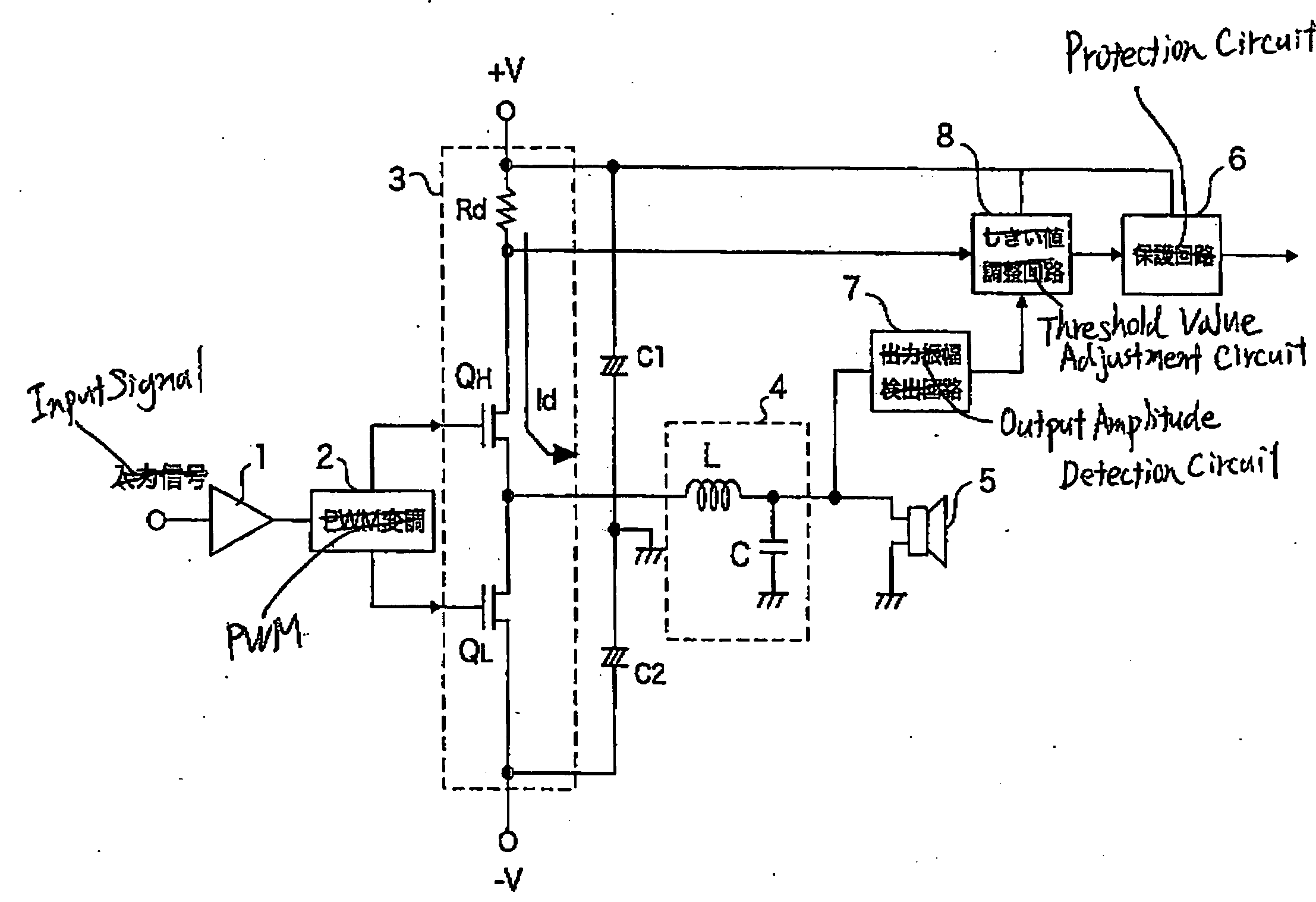
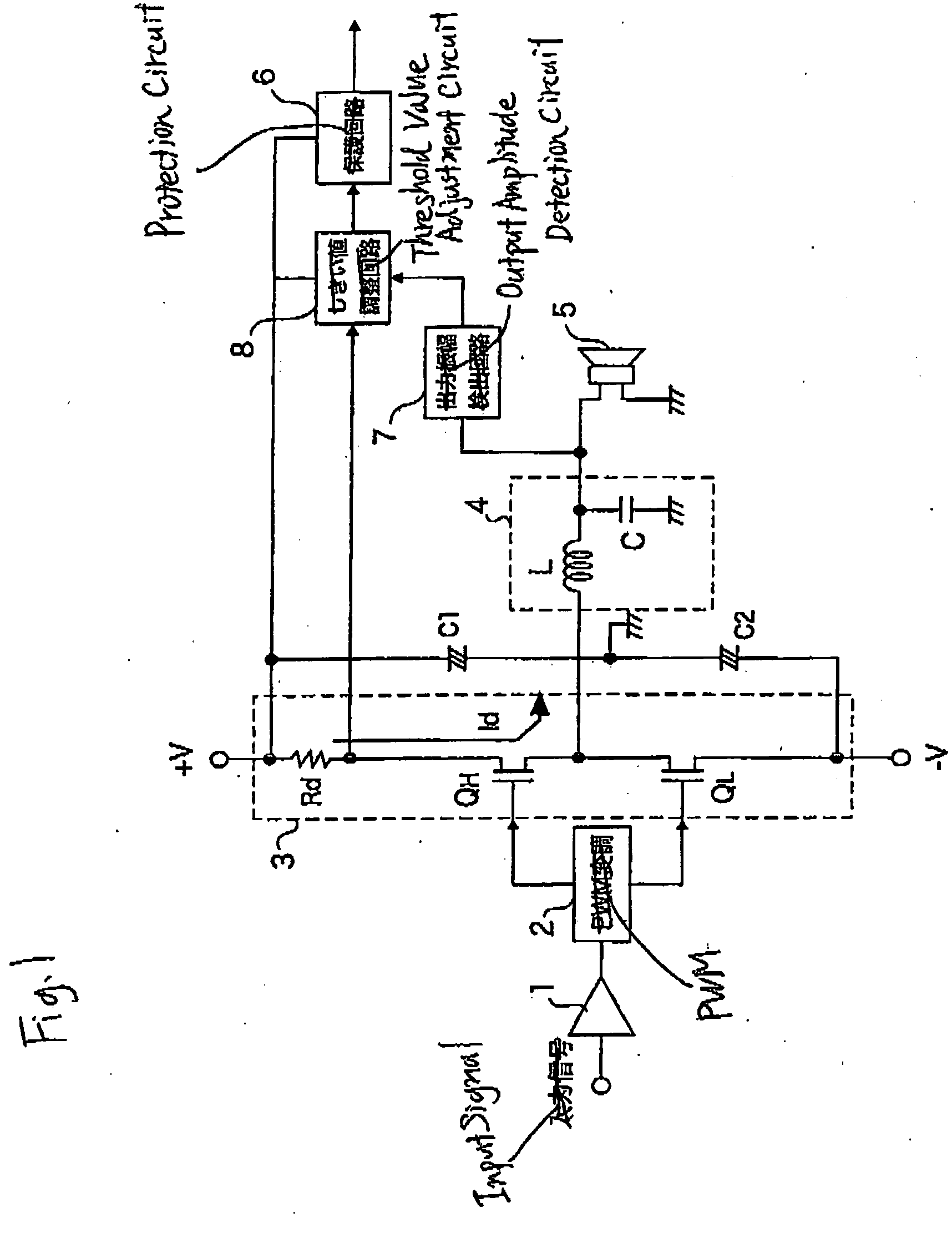
[0036]FIG. 1 is a block diagram showing the schematic configuration of a digital amplifier according to an embodiment of the invention. In FIG. 1, the reference numeral 1 designates an input amplifier for amplifying an analog input signal; 2, a PWM (Pulse Width Modulation) modulation portion for generating a PWM signal with a pulse width corresponding to the amplitude of the analog signal from the input amplifier 1 and outputting a driving signal for driving switching devices QH and QL of a class D amplifier stage 3; 3, the class D amplifier stage (switching stage) having the switching devices QH and QL, which are MOSFETs or the like, connected in series; C1 and C2, decoupling capacitors; 4, an output filter (low pass filter) for reproducing an analog signal from a pulse signal outputted from the class D amplifier stage 3; and 5, a speaker serving as a load.

[0037] As shown in FIG. 1, a current detection resistor Rd is inserted between the high-side switching device QH and a positiv...


PUM


Abstract

A threshold value adjustment circuit for adjusting a predetermined threshold value is provided in a stage followed by a protection circuit which starts protection operation when a load current flowing into an MOSFET exceeds the threshold value. A voltage proportional to a drain current and generated between the opposite ends of a current detection resistor Rd inserted between the high-side MOSFET and a positive power supply +V, and an output of an output voltage detection circuit for detecting the voltage amplitude of an analog signal from a low pass filter for modulating an output of a class D amplifier stage are inputted to the threshold value adjustment circuit. The threshold value adjustment circuit adjusts the threshold value in such a manner that a limit current of the MOSFET is set as the threshold value when the output voltage is large, and protection operation is started in response to a lower current than the limit current when the output voltage is small.

Description

BACKGROUND OF THE INVENTION [0001] The present invention relates to a digital amplifier (class D amplifier), and particularly relates to an overcurrent detection circuit of the digital amplifier. [0002] In recent years, digital amplifiers each provided for converting an analog signal such as a music signal into a pulse signal, amplifying the power of the pulse signal and outputting the amplified pulse signal through a low pass filter have been used broadly due to their high efficiency. [0003] As a protection circuit in such a digital amplifier, there is known a current limiter (Non-Patent Document 1). [0004]FIG. 7 is a view showing a configuration example of such a digital amplifier provided with a current limiter. [0005] In FIG. 7, the reference numeral 51 designates an input amplifier; 52, a PWM modulation portion for generating a pulse signal in accordance with the amplitude of an input analog signal and outputting a driving signal for driving a class D amplifier stage; 53, the c...

Claims


Application Information

Patent Timeline
Patent Type & Authority Applications(United States)
IPC IPC(8): H02H3/08
CPCH03F1/52H03F3/217H03F2200/351
Inventor KANOH, MASAYANORO, MASAO
Owner YAMAHA CORP
Learn More