
Imaging system for three-dimensional reconstruction of surface profiles

a three-dimensional reconstruction and imaging system technology, applied in the field of three-dimensional reconstruction of surface profiles, can solve the problems of many difficulties in inspecting the surface of the profile, inapplicability of traditional inspection techniques, and more stringent requirements on process control and quality assuran

Active Publication Date: 2006-06-22
ASM ASSEMBLY AUTOMATION LTD
View PDF3 Cites 25 Cited by
  • Summary
  • Abstract
  • Description
  • Claims
  • Application Information

AI Technical Summary

Benefits of technology

[0009] It is therefore an object of the invention to seek to provide a system utilizing a method for the three-dimen

Problems solved by technology

However, the reduced dimensions of the devices also lead to more stringent requirements on process control and quality assurance.
A particular challenge relates to the development of vision techniques for three-dimensionally inspecting the surfaces of these smaller devices accurately and efficiently.
However, the small size of the wafer bumps, which typically have diameters of about 60 microns, mean that traditional inspection technologies, such as techniques for inspecting solder bumps on printed circuit boards, are inapplicable.
In addition, the highly specular and textureless nature of these devices lead to many difficulties in inspecting their surfaces.
However, the laser triangulation method is limited by slow speed and low resolution.
Confocal microscopy involves moving parts and has limitations in its operation speed.
Gray-level pattern projection has the problems of image brightness saturation and high sensitivity to noise.
For this reason it has intrinsic problems like brightness saturation, multi-reflection, and noise or disturbance to gray-level brightness.

Method used


Image

  • Imaging system for three-dimensional reconstruction of surface profiles
  • Imaging system for three-dimensional reconstruction of surface profiles
  • Imaging system for three-dimensional reconstruction of surface profiles

Examples


Embodiment Construction

[0017] Basic Imaging System

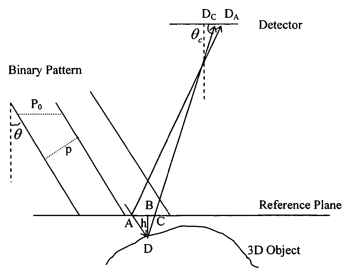
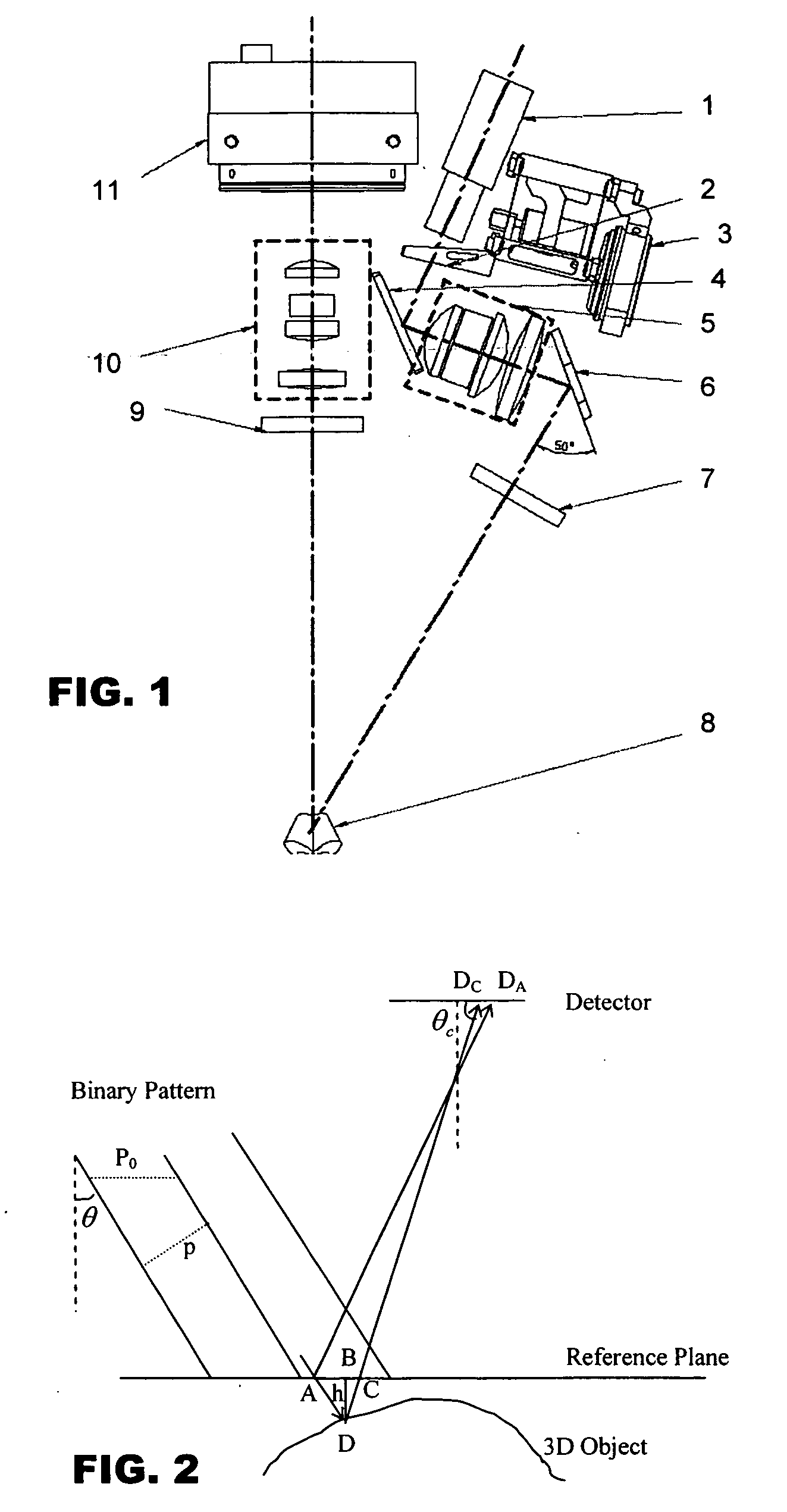
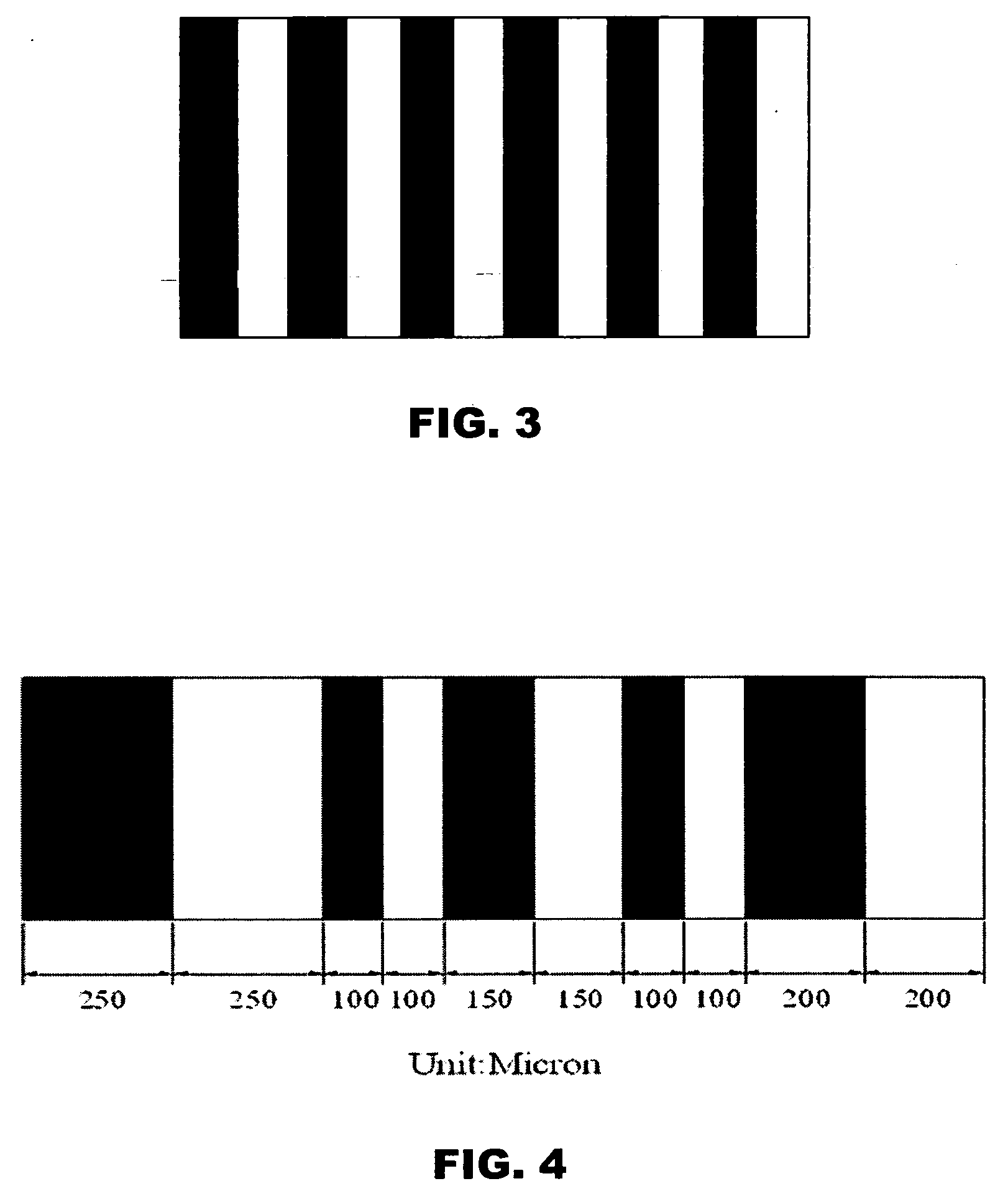
[0018] The preferred embodiment of the invention utilizes principles of pattern projection. The pattern projection method involves projecting a light pattern onto a surface to be inspected and capturing images of the illuminated surface from one or more points of view. If the pattern is generated in discrete form, i.e. with n-level digitization, and most preferably in binary form, problems of image brightness saturation and sensitivity to noise can be relieved, since only bright or dark areas need to be determined instead of having to take into account gray-level intensity. By changing the position of the fixed binary pattern on the illuminated surface every time an image is taken, a binary code can be produced for each position on the illuminated surface from the sequence of images taken. If the change in the binary pattern is suitably selected, a unique binary code can be produced for each surface position along an axis. With such unique binary codes pr...


PUM


Abstract

A system for three-dimensional reconstruction of a surface profile of a surface of an object is provided that utilizes a binary pattern projected onto the surface of the object. A binary string consisting of a series of “1”s and “0”s is first created, and a binary pattern of light that is constructed in accordance with the binary string such that bright and dark bands of light of equal widths correspond to “1”s and “0”s from the binary string respectively is projected onto the surface. The binary pattern is shifted with respect to the surface multiple times, during which an image of the binary pattern illuminating the surface is obtained at each position of the binary pattern. Thereafter, a height of each predetermined point on the surface is calculated relative to a reference plane based upon the images cumulatively obtained at said predetermined point.

Description

CROSS REFERENCE TO RELATED APPLICATION [0001] This application claims the benefit and priority of U.S. Provisional Application Ser. No. 60 / 637,133 filed on Dec. 17, 2004, and entitled IMAGING SYSTEM FOR THREE-DIMENSIONAL RECONSTRUCTION OF SURFACE PROFILES, the disclosure of which is incorporated herein by reference.FIELD OF THE INVENTION [0002] The invention relates to the three-dimensional reconstruction of a surface profile of an object by projecting a variable light pattern onto the surface to thereby determine the heights of multiple points on the surface. BACKGROUND [0003] As the electronic industry advances rapidly towards manufacturing smaller, lighter, faster, and cheaper products, area array packages including Ball-Grid Array (“BGA”) packages, Chip-Scale Packages (“CSP”), flip chips, wafer bumping and wafer-level packaging (“WLP”) are increasingly becoming the focus of IC packaging technology. Area array packages help to improve device performance and manufacturability, and...

Claims


Application Information

Patent Timeline
IPC IPC(8): G01B11/24
CPCG01B11/2527
Inventor CHUNG, CHI KIT RONALCHENG, JUNLAM, Y. EDMUNDFUNG, SHUN MING KENNETHWANG, FANLEUNG, WING HONG
Owner ASM ASSEMBLY AUTOMATION LTD
Learn More