
Liquid crystal display panel

a liquid crystal display panel and display panel technology, applied in non-linear optics, instruments, optics, etc., can solve the problems of limited number of users of such devices, inconvenient use of small liquid crystal display panels for mobile devices, and inability to achieve high contrast efficiency

Inactive Publication Date: 2006-06-22
JAPAN DISPLAY WEST
View PDF9 Cites 21 Cited by
  • Summary
  • Abstract
  • Description
  • Claims
  • Application Information

AI Technical Summary

Benefits of technology

[0034] In view of the above-mentioned, the present inventors aim to provide an MVA type of liquid crystal display panel having high contrast efficiency, where contrast reduction caused by the inclination of liquid crystal molecules which is induced by a potential difference that occurs between a scanning line and a common electrode can be controlled even in a liquid crystal display panel employing pixel electrodes whose corner portions are chamfered.
[0036] With the above-described means, it is possible to provide an MVA type of liquid crystal display panel having high contrast efficiency, where contrast reduction caused by the inclination of liquid crystal molecules which is induced by a potential difference that occurs between a scanning line and a common electrode can be controlled.
[0037] Further, by forming the protruding electrode particularly in the light transmission area of the liquid crystal display panel, the conspicuously adverse affect of the potential difference between the scanning line and the common electrode can be effectively suppressed.
[0038] Furthermore, by arranging the protruding electrode so as to overlap the scanning line, the above-described excellent effect is not impaired even if a slight mask slippage or the like occurs during manufacturing.

Problems solved by technology

On the other hand, traditionally, the demand for a wide viewing angle for liquid crystal display panels used in mobile devices such as cell phones or the like was not so high because the number of users for such devices was limited.
In developing the MVA type semi-transmissive liquid crystal display panel the inventors also initially experimented on the shapes of protrusions and slits formed in the conventional zigzag state as shown in FIG. 6, but noted that they were not suitable for small liquid crystal display panels for use in mobile devices.
It is believed that this is due to the fact that the size of recently used pixels of small liquid crystal display panels producing high definition has been greatly reduced, while the zigzag-shaped protrusions and slits used in conventional medium and small sized liquid crystal display panels produced poor visual quality for TVs and monitors to which they were applied.

Method used


Image

  • Liquid crystal display panel
  • Liquid crystal display panel
  • Liquid crystal display panel

Examples


Embodiment Construction

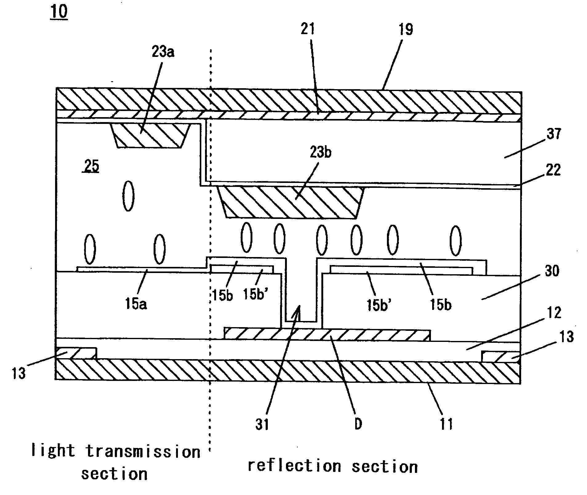
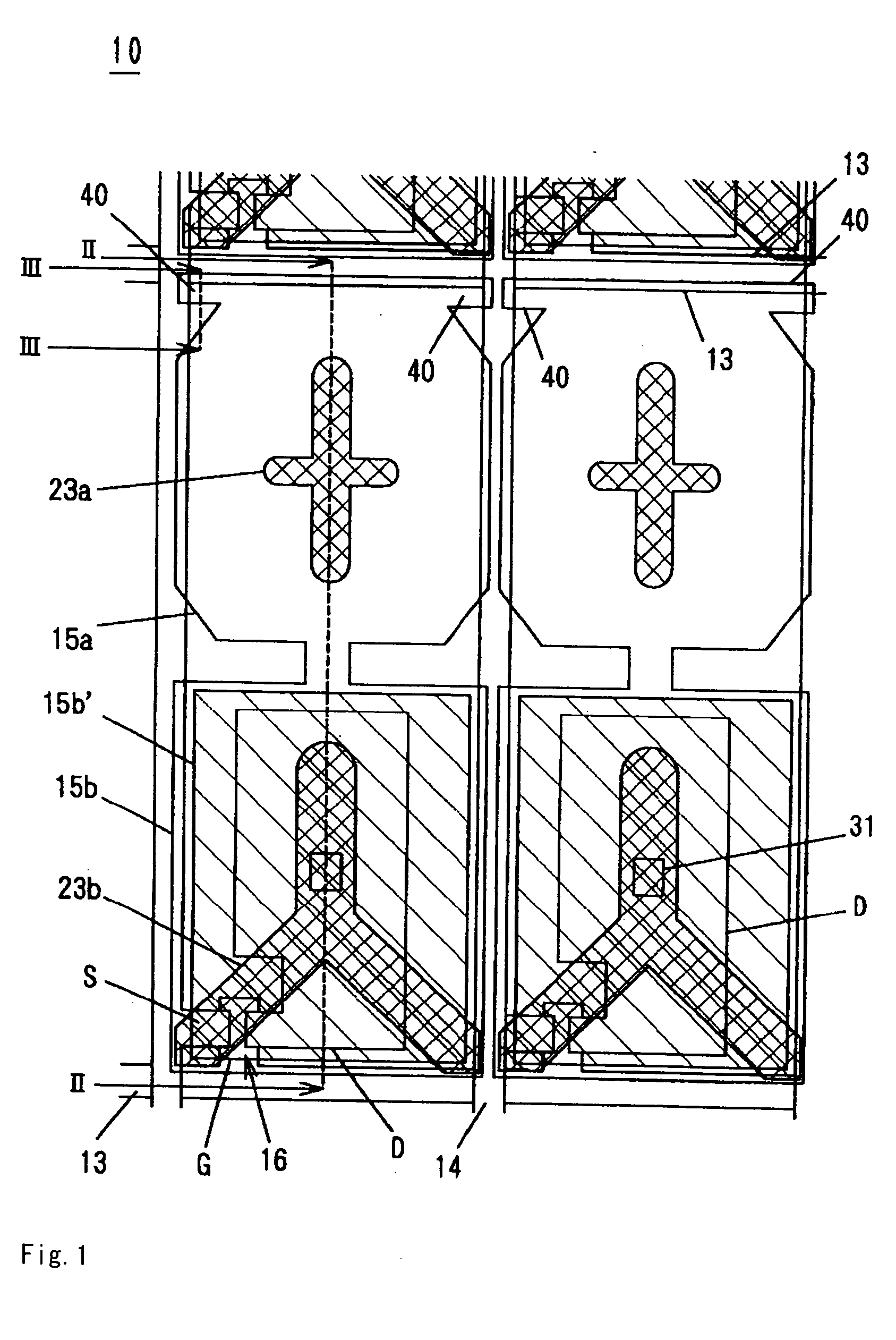
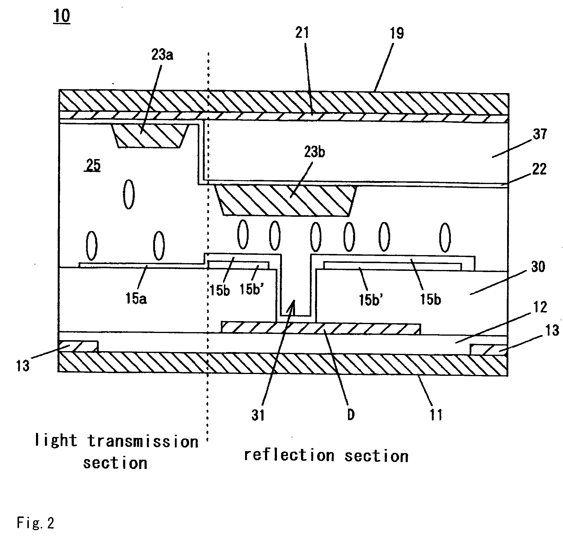
[0049] Examples of the present invention will hereafter be described with reference to the drawings. Although the following examples show the embodiments of a transmissive or semi-transmissive liquid crystal display panel pertaining to the technical concept of the present invention, they are not intended to limit the applicability of the present invention. Further, the liquid crystal display panel described in the examples shows a small liquid crystal display panel mainly used in the display section for mobile devices such as digital cameras and cell phones, and illustrates a panel of about 2.2 inches with a definition exceeding 300 ppi, having 640×480 (VGA) pixels or 320×240 pixels (QVGA). The size of one pixel is also significantly smaller than that of a liquid crystal display panel for a TV set of 40 inches or the like.

[0050]FIGS. 1 and 2 show the semi-transmissive liquid crystal display panel according to Example 1. Note that FIG. 1 is a schematic plane view of two pixel areas ...


PUM


Abstract

An MVA type liquid crystal display panel of the present invention comprises a first substrate where a light transmission section consisting of a pixel electrode 15a, whose corner portions are chamfered, is formed at each position partitioned by scanning lines 13 and signal lines 14 that are arranged in a matrix state, in which a protruding electrode 40 extending from the pixel electrode 15a is formed between the chamfered position of the corner portion and the scanning line 13 to prevent the inclination of liquid crystal molecules due to the effect of the potential difference occurring between the scanning line and a common electrode. According to the present invention, it is possible to provide an MVA type of liquid crystal display panel having high contrast, where contrast reduction caused by the inclination of liquid crystal molecules due to the effect of the potential difference occurring between the scanning line and a common electrode is controlled, even where the liquid crystal display panel employs pixel electrodes with chamfered corner portions.

Description

BACKGROUND OF THE INVENTION [0001] 1. Field of the Invention [0002] The present invention relates to a liquid crystal display panel, particularly to a transmissive or semi-transmissive liquid crystal display panel of the multi-domain vertically aligned (MVA) type having good display quality, where discrimination is suppressed. [0003] 2. Background Art [0004] Liquid crystal display devices are generally thin and lightweight and have a low level of power consumption, and are broadly used for various items, from portable terminals to large-sized television sets. The vertically aligned (VA) type of liquid crystal display panel is known to be used in liquid crystal display devices. [0005] In a VA type of liquid crystal display panel 60, as shown in FIG. 5, liquid crystal having negative dielectric anisotropy is filled between a pair of substrates 62, 64, a pixel electrode 61 being arranged on the substrate 62, and a common electrode 63 being arranged on the substrate 64. Alignment films ...

Claims


Application Information

Patent Timeline
IPC IPC(8): G02F1/1343G02F1/1335
CPCG02F1/133707G02F1/134309G02F1/1393G02F1/1343
Inventor TANAKA, SHINICHIRO
Owner JAPAN DISPLAY WEST
Learn More